Reciprocating compressor

A compressor and reciprocating technology, applied in the direction of liquid variable displacement machinery, mechanical equipment, engine components, etc., can solve the problems of exhaust valve system damage, increase valve chamber, etc.

Active Publication Date: 2020-05-26
ATLAS COPCO CREPELLE
View PDF1 Cites 0 Cited by
  • Summary
  • Abstract
  • Description
  • Claims
  • Application Information

AI Technical Summary

Problems solved by technology

[0004] It has been shown that in reciprocating compressor operation, high pulsation levels are manifested in the discharge valve systems which can lead to serious damage to these discharge valve systems
[0005] Known measures to attempt to solve this problem include increasing the volume of the valve chamber or adding a large external volume; however, in particular, limitations are encountered in terms of available integration space, since the overall size of the compressor is usually fixed

Method used


Image

  • Reciprocating compressor
  • Reciprocating compressor
  • Reciprocating compressor

Examples


Embodiment Construction

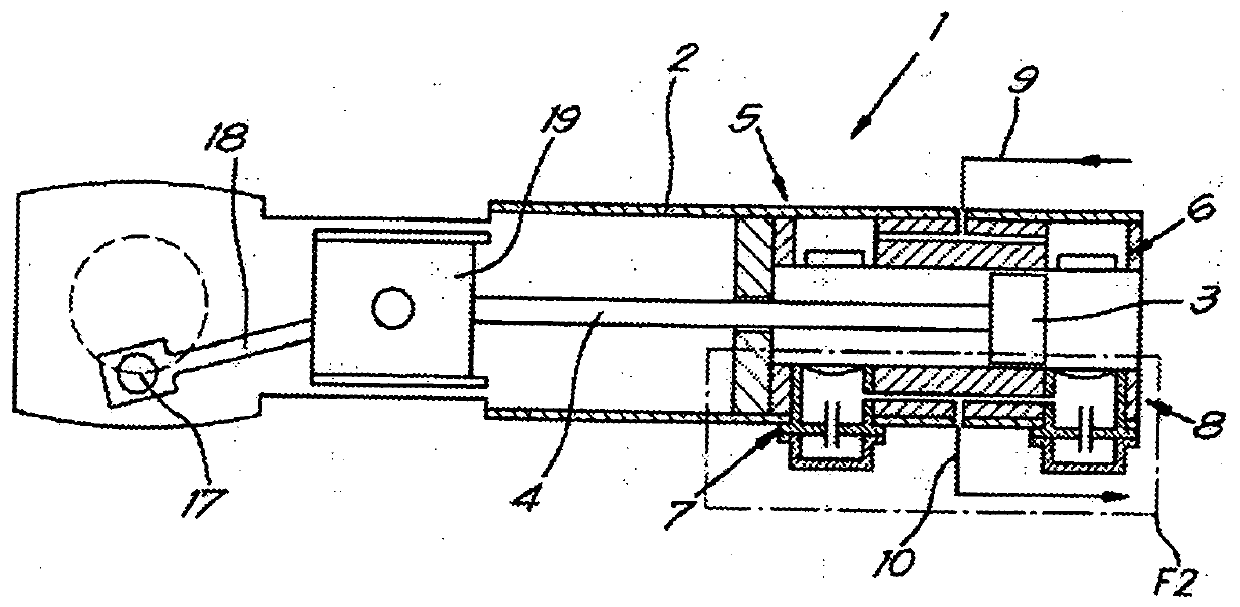
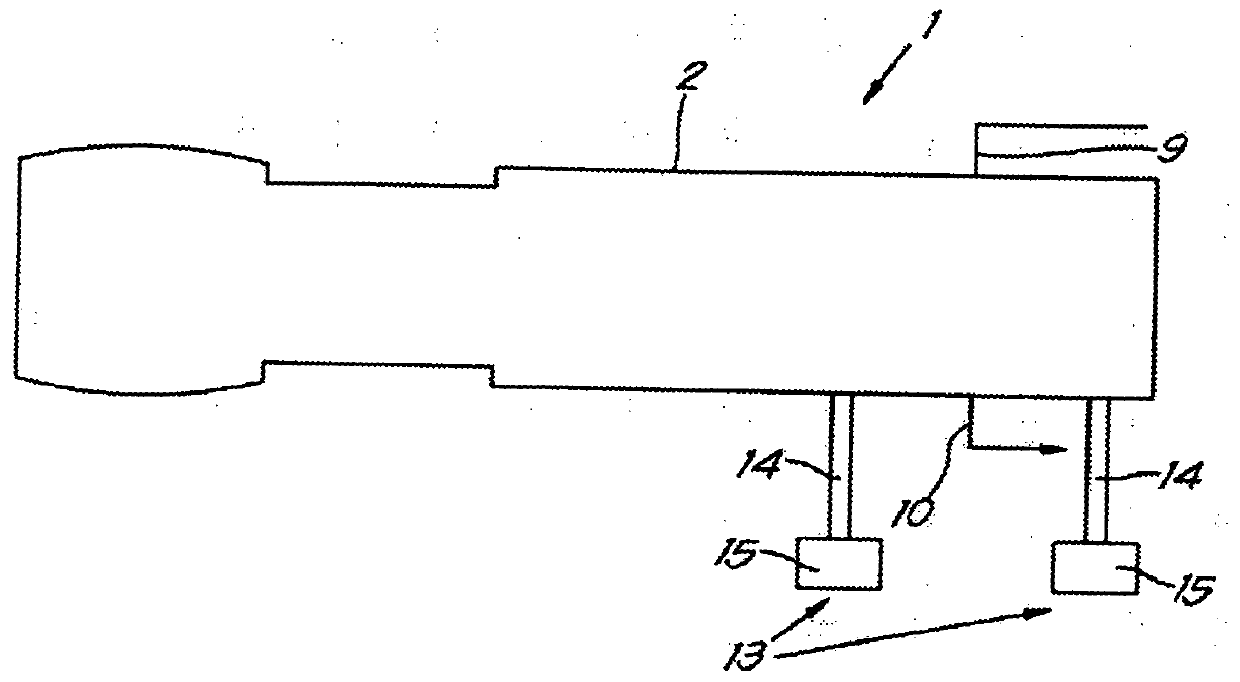
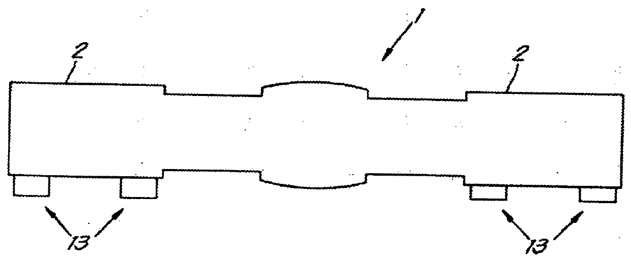
[0018] exist figure 1 with 2 In , a reciprocating compressor 1 according to the invention is shown. Said compressor 1 comprises a cylinder 2 comprising an internal cylindrical cavity in which a piston 3 will be housed. Said piston 3 movable inside said cavity forms part of a device capable of reciprocating movement, which also includes a piston rod 4 .

[0019] The compressor 1 also includes drive means configured to move said device in reciprocating motion, said drive means optionally including a crankshaft.

[0020] Said piston 3 divides said cavity into a first chamber and a second chamber, denoted by the terms "head side end chamber" and "crankshaft side end chamber" respectively , each of the first and second chambers is connected to a respective suction duct 9 and exhaust duct 10 via a respective suction valve system 5 or 6 and an exhaust valve system 7 or 8 .

[0021] Said suction valve systems 5 and 6 and said discharge valve systems 7 and 8 each comprise a valve h...


PUM


Abstract

A reciprocating compressor comprising a cylinder (2) and a piston (3), the piston dividing a cavity in the cylinder (2) into a first chamber and a second chamber, the first chamber and the second chamber are connected to the suction pipe (9) and the discharge pipe (10) via the corresponding suction valve system (5, 6) and the discharge valve system (7, 8), the suction valve and the discharge valve The systems (5‑8) each comprise a valve casing and a valve body (12) defining a valve chamber (11), said reciprocating compressor (1) is also equipped with a container (13) defining a volume through which a A conduit (14) is in fluid communication with at least one exhaust valve chamber of said exhaust valve system (7; 8).

Description

technical field [0001] The present invention relates to a reciprocating compressor comprising a cylinder in which a cavity is arranged and means capable of reciprocating movement, said means comprising a piston and a piston rod, said reciprocating compressor further comprising a cylinder configured to the drive part of said device moving in reciprocating motion, said piston dividing said cavity into a first chamber and a second chamber denoted by the terms head-side end chamber and crankshaft-side end chamber respectively, Each of the first chamber and the second chamber is connected to a suction duct and an exhaust duct via a corresponding suction valve system and an exhaust valve system, each of which includes a valve chamber defining a The valve casing and the valve body are movable between a first closed position and a second open position, in the first closed position, the first chamber or the second chamber is fluidly disconnected from the valve chamber, in the In an op...

Claims


Application Information

Patent Timeline
Patent Type & Authority Patents(China)
IPC IPC(8): F04B5/02F04B39/00F04B39/10F04B53/10
CPCF04B5/02F04B39/0027F04B39/0066F04B39/10F04B53/10F04B39/123F16K47/00
Inventor B·M·博代纳
Owner ATLAS COPCO CREPELLE
Why Eureka
Try Eureka