Magnetic sensors using the inverse spin Hall effect

A magnetic sensor and spin Hall technology, applied in the manufacture of flux-sensitive magnetic heads, instruments, magnetic recording, etc., can solve problems such as increased data density

Active Publication Date: 2021-09-21
WESTERN DIGITAL TECH INC
View PDF6 Cites 0 Cited by
  • Summary
  • Abstract
  • Description
  • Claims
  • Application Information

AI Technical Summary

Problems solved by technology

Smaller spacing between shields leads to increased data density by increasing the bits that can be recorded and detected on a given length of data track

Method used


Image

  • Magnetic sensors using the inverse spin Hall effect
  • Magnetic sensors using the inverse spin Hall effect
  • Magnetic sensors using the inverse spin Hall effect

Examples


Embodiment Construction

[0026] The following description is of the best mode currently contemplated for carrying out the invention. This description is intended to illustrate the general principles of the invention and is not meant to limit the inventive concepts claimed herein.

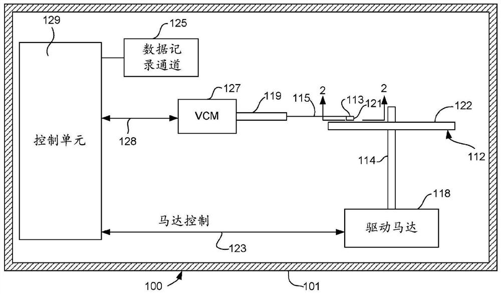
[0027] now refer to figure 1 , shows a disk drive / data storage system 100 . Disk drive 100 includes housing 101 . At least one rotatable disk 112 is supported on a spindle 114 and rotated by a disk drive motor 118 . The magnetic recording on each disk may be in the form of a circular pattern of concentric data tracks (not shown) on disk 112 .

[0028] At least one slider 113 is positioned adjacent to the magnetic disk 112 , each slider 113 supporting one or more magnetic head assemblies 121 . As the disk rotates, the slider 113 moves in and out over the disk surface 122 so that the head assembly 121 can access different tracks of the disk for writing desired data. Each slider 113 is attached to an actuator arm 119 by a...


PUM


Abstract

The invention discloses a magnetic sensor which generates signals based on the inverse spin Hall effect. The sensor includes a magnetic free layer and a non-magnetic conductive spin Hall layer positioned adjacent to the magnetic free layer. The circuit is configured to supply current through the magnetic free layer in a direction generally perpendicular to the plane of the layer or perpendicular to the plane defined by the interface between the magnetic free layer and the spin Hall layer. The magnetic free layer and the spin Hall layer. The inverse spin Hall effect induces a voltage in the spin Hall layer due to the current, and the voltage changes with respect to the orientation of the magnetization of the magnetic free layer. Circuitry is provided for measuring the voltage in the spin Hall layer in a direction substantially perpendicular to the direction of the current flow.

Description

[0001] Cross References to Related Applications [0002] This application claims priority to US Application 15 / 385595, filed December 20, 2016, which is incorporated by reference in its entirety. technical field [0003] The present invention relates to magnetic data recording, and more particularly to magnetic readout sensors that utilize the inverse spin Hall effect to detect the presence of a magnetic field. Background technique [0004] At the heart of many computer systems is a component called a disk drive. The disk drive includes a rotating disk, a read head and a write head suspended by a suspension arm adjacent to the surface of the rotating disk, and a selected location for swinging the suspension arm to place the read head and write head on the rotating disk. Actuator on track. The read and write heads are positioned directly on a slider with an air bearing surface (ABS). When the disk is not spinning, the suspension arm biases the slider into contact with the ...

Claims


Application Information

Patent Timeline
Patent Type & Authority Patents(China)
IPC IPC(8): G01R33/07H01J43/06G11B5/33G11B5/37
CPCG01R33/075G11B5/1278G11B5/332G11B5/372G11B5/374H01J43/06
Inventor P·A·凡德赫顿Q·勒K·S·霍X·刘G·M·巴奥德阿布克尔克
Owner WESTERN DIGITAL TECH INC
Why Eureka
Try Eureka