[0025] In order to make the objectives, technical solutions, and advantages of the embodiments of the present invention clearer, the technical solutions of the embodiments of the present invention will be described clearly and completely in conjunction with the accompanying drawings of the embodiments of the present invention. Obviously, the described embodiments are part of the embodiments of the present invention, rather than all of the embodiments. Based on the described embodiments of the present invention, all other embodiments obtained by a person of ordinary skill in the art without creative work shall fall within the protection scope of the present invention.
[0026] Unless otherwise defined, the technical or scientific terms used in the present invention shall have the usual meanings understood by those with ordinary skills in the field to which the present invention belongs. The "first", "second" and similar words used in the present invention do not indicate any order, quantity or importance, but are only used to distinguish different components. "Include" or "include" and other similar words mean that the element or item appearing before the word covers the element or item listed after the word and its equivalents, but does not exclude other elements or items. Similar words such as "connected" or "connected" are not limited to physical or mechanical connections, but may include electrical connections, whether direct or indirect. "Up", "Down", "Left", "Right", etc. are only used to indicate the relative position relationship. When the absolute position of the described object changes, the relative position relationship may also change accordingly.
[0027] In order to keep the following description of the embodiments of the present invention clear and concise, the present invention omits detailed descriptions of known functions and known components.
[0028] The first embodiment of the present invention provides a gas sensor. The structure of the gas sensor is shown as figure 1 Shown, including:
[0029] Base 1, gas sensor 2, thermal circuit 3; gas sensor 2, set on the first surface of substrate 1, thermal circuit 3, set on substrate 1, used to set the temperature of the gas sensor 2 in the working environment When the temperature is lower than the preset temperature threshold, the gas sensor 2 is heated.
[0030] Since the heat-sensitive circuit heats the gas-sensitive device, the embodiment of the present invention figure 1 The position of the thermal circuit is directly arranged in the lower part of the base 1, but it is only a schematic structural diagram, and does not limit the position of the thermal circuit in the embodiment of the present invention.
[0031] The embodiment of the present invention is provided with a thermal circuit in the gas sensor, which can heat the gas sensor through the thermal circuit when the working environment temperature of the gas sensor is low, so as to ensure that the working environment temperature of the gas sensor will not be low. The measurement accuracy of the gas sensor is ensured, and the function of wide temperature operation of the gas sensor is realized.
[0032] In specific implementation, the thermal circuit 3 may include: a heating film 31 arranged on a second surface of the base 1 opposite to the first surface to heat the gas sensor 2. The aforementioned substrate may be glass. The heating film and the gas sensor are integrated into a whole by optical full bonding, so as to uniformly heat the gas sensor.
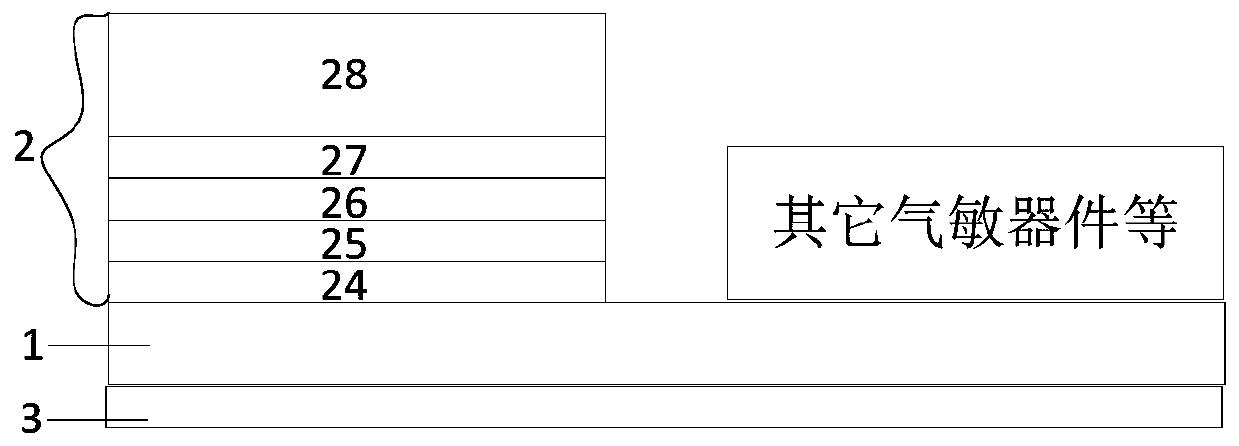
[0033] The existing substrate is usually a glass substrate, and multiple gas sensors are arranged on a glass substrate, such as figure 2 As shown, since multiple gas sensors are arranged on one glass substrate, the area of the glass substrate is larger than the sum of the areas of the multiple gas sensors.
[0034] figure 2 The numbers 24 to 28 in the gas sensor form the gas sensor. In the TFT structure of the traditional liquid crystal display, the two kinds of gate metal layers of different materials together form the gate metal layer, that is, the gate metal layer is composed of 24 and 25. The gate metal layer is plated with a layer of tin oxide to form a tin oxide layer 27. The gate metal layer and the tin oxide layer 27 are separated by an insulating layer 26. The tin oxide layer 27 is provided with other metal layers 28, such as Gas sensitive materials such as zinc oxide. When the other metal layer 28 absorbs the gas to be measured, the impedance of the gate and source changes, and the concentration of the gas to be measured is determined by collecting the voltage change between the drain and the source.
[0035] If in figure 2 The gas sensor shown is equipped with a thermal circuit, and the area of the heating film with the thermal circuit can be the same as the area of the substrate, such as image 3 Shown.
[0036] Of course, in order to reduce the amount of heating film, it can also be configured that the area of each heating film is the same as the area occupied by each gas sensor on the first surface, and the gas sensors and the heating film are arranged in one-to-one correspondence, for example, Figure 4 Shown is a schematic diagram of two gas sensors arranged on a substrate.
[0037] If the heating film keeps heating the gas sensor, power consumption will increase. In order to reduce power consumption and enable automatic heating of the gas sensor, the structure of the above gas sensor can also be as Figure 5 As shown, the thermal circuit may further include: a thermocouple 32, which is arranged on the first surface of the base body and has a predetermined distance from the gas sensor, and is used to detect the working environment temperature of the gas sensor; a controller 33, and the thermocouple 32 is connected to the heating film 31, and is used to trigger the heating film to work when the working environment temperature is lower than the preset temperature threshold.
[0038] The thermocouple 32 includes a first material body 321 and a second material body 322. The first material body 321 is arranged on the first surface of the base body 1, and the second material body 322 is arranged on the first material body 321. The body 321 and the second material body 322 use different materials. Among them, the materials used in the first material body and the second material body include at least one of the following: a conductor and a semiconductor. If the first material body is metal A, the second material body needs to be a material other than metal A, for example, metal B or semiconductor C.
[0039] The basic principle of the above thermocouple is that when there are two different conductors or semiconductors A and B forming a loop, and their two ends are connected to each other, as long as the temperatures at the two nodes are different, an electromotive force will be generated in the loop. The direction and magnitude of the electromotive force It is related to the material of the conductor and the temperature of the two nodes. When the controller detects that there is an electromotive force, it determines the magnitude of the electromotive force, such as detecting the current voltage; when the detected voltage is greater than the preset voltage, it means that the temperature change has exceeded the preset temperature threshold, and the heating film can be started. . In specific implementation, the temperature of one of the two material bodies of the thermocouple can be set as the reference temperature, and the temperature of the other material body can be set as the working temperature, and then the temperature change can be monitored. The specific process will not be repeated here.
[0040] Since the heating film needs to obtain heat energy, the above-mentioned thermal circuit may further include a power supply for supplying power to the heating film and/or the controller.
[0041] Above Figure 1 to Figure 5 They are all examples of the side structure of the gas sensor and do not limit the structure of the gas sensor.
[0042] The embodiment of the present invention accurately measures the temperature around the device, and automatically triggers the thermal circuit for heating in a low temperature environment, thereby realizing the function of wide temperature operation of the gas sensor.
[0043] The second embodiment of the present invention provides a method for controlling a gas sensor. The gas sensor provided in the first embodiment is applied. The process of the method is as follows: Image 6 As shown, it includes steps S601 to S602:
[0044] S601: Detect whether the current working environment temperature of the gas sensor is lower than a preset temperature threshold;
[0045] S602: When the temperature of the working environment is lower than the preset temperature threshold, send a control signal to trigger the operation of the heating film.
[0046] The control method implemented by the embodiment of the present invention is implemented inside the controller of the thermal circuit. When the controller receives the electromotive force from the thermocouple, it will determine the current working environment temperature change according to the change of the electromotive force, and further combine the basis of the thermocouple The reference temperature determines the current working environment temperature, and then compares it with the preset temperature threshold. Once it is lower than the preset temperature threshold, it can be determined to send a control signal that triggers the operation of the heating film to make the heating film heat the gas sensor.
[0047] In implementation, before detecting whether the current working environment temperature of the gas sensor is lower than the preset temperature threshold, it is also necessary to determine the direction and magnitude of the electromotive force generated by the thermocouple, and then determine the gas according to the direction and magnitude of the electromotive force and the material of the thermocouple. The current working environment temperature of the sensitive device.
[0048] In order to ensure that the power consumption is within a reasonable range, after sending the control signal that triggers the heating film to work, it can also detect whether the current working environment temperature of the gas sensor is higher than the preset temperature threshold; when the working environment temperature is higher than the preset temperature threshold In the case of sending a control signal to trigger the heating film to stop working.
[0049] The embodiment of the present invention can automatically adjust the temperature of the working environment of the gas sensor to ensure that the temperature of the working environment of the gas sensor will not be low, thereby ensuring the measurement accuracy of the gas sensor and realizing the function of wide temperature operation of the gas sensor.
[0050] The third embodiment of the present invention provides a storage medium that stores a computer program, and when the computer program is executed by a processor, the method provided in any embodiment of the present invention is implemented. For example, the storage medium may exist in the form of a controller. , The computer program implements the following steps S1 to S2:
[0051] S1, detecting whether the current working environment temperature of the gas sensor is lower than a preset temperature threshold;
[0052] S2: When the temperature of the working environment is lower than the preset temperature threshold, send a control signal to trigger the operation of the heating film.
[0053] When the storage medium of the embodiment of the present invention receives the electromotive force from the thermocouple, it will determine the current working environment temperature change according to the change of the electromotive force, and further combine the basic reference temperature of the thermocouple to determine the current working environment temperature, and then compare it with the preset The temperature threshold is compared, and once it is lower than the preset temperature threshold, a control signal that triggers the operation of the heating film can be determined to send the heating film to heat the gas sensor.
[0054] After the computer program is executed by the processor to send the control signal to trigger the heating film, the processor also executes the following steps: detecting whether the current working environment temperature of the gas sensor is higher than the preset temperature threshold; when the working environment temperature is higher than the preset temperature When the temperature threshold is set, a control signal that triggers the stopping of the heating film is sent.
[0055] The computer program is executed by the processor to detect whether the current working environment temperature of the gas sensor is lower than the preset temperature threshold. The processor also executes the following steps: determine the direction and magnitude of the electromotive force generated by the thermocouple; according to the direction of the electromotive force And the size, and the material of the thermocouple determine the current working environment temperature of the gas sensor.
[0056] The embodiment of the present invention can automatically adjust the temperature of the working environment of the gas sensor to ensure that the temperature of the working environment of the gas sensor will not be low, thereby ensuring the measurement accuracy of the gas sensor and realizing the function of wide temperature operation of the gas sensor.
[0057] Optionally, in this embodiment, the above-mentioned storage medium may include, but is not limited to: U disk, read-only memory (ROM, Read-Only Memory), random access memory (RAM, Random Access Memory), mobile hard disk, magnetic disk or optical disk Various media that can store program codes. Optionally, in this embodiment, the processor executes the method steps described in the foregoing embodiment according to the program code stored in the storage medium. Optionally, for specific examples in this embodiment, reference may be made to the examples described in the above-mentioned embodiments and optional implementation manners, and details are not described herein again in this embodiment. Obviously, those skilled in the art should understand that the above-mentioned modules or steps of the present invention can be implemented by a general computing device, and they can be concentrated on a single computing device or distributed on a network composed of multiple computing devices. Above, alternatively, they can be implemented with program codes executable by the computing device, so that they can be stored in the storage device for execution by the computing device, and in some cases, can be executed in a different order than here. Perform the steps shown or described, or fabricate them into individual integrated circuit modules separately, or fabricate multiple modules or steps of them into a single integrated circuit module for implementation. In this way, the present invention is not limited to any specific combination of hardware and software.
[0058] In addition, although the exemplary embodiments have been described herein, the scope includes any and all implementations with equivalent elements, modifications, omissions, combinations (for example, crossover schemes of various embodiments), adaptations, or changes based on the present invention example. The elements in the claims will be interpreted broadly based on the language adopted in the claims, and are not limited to the examples described in this specification or during the implementation of this application, and the examples will be interpreted as non-exclusive. Therefore, this specification and examples are intended to be regarded as examples only, and the true scope and spirit are indicated by the following claims and the full scope of their equivalents.
[0059] The above description is intended to be illustrative and not restrictive. For example, the above examples (or one or more of them) can be used in combination with each other. For example, a person of ordinary skill in the art may use other embodiments when reading the above description. In addition, in the foregoing specific embodiments, various features may be grouped together to simplify the present invention. This should not be construed as an intent that an unclaimed disclosed feature is necessary for any claim. On the contrary, the subject matter of the present invention may be less than all the features of a specific disclosed embodiment. Thus, the following claims are incorporated herein as examples or embodiments in the detailed description, wherein each claim independently serves as a separate embodiment, and it is considered that these embodiments can be combined with each other in various combinations or permutations. The scope of the present invention should be determined with reference to the appended claims and the full scope of equivalents entitled by these claims.
[0060] A number of embodiments of the present invention have been described in detail above, but the present invention is not limited to these specific embodiments. Those skilled in the art can make many variations and modified embodiments based on the concept of the present invention. These variations and modifications All should fall within the scope of protection claimed by the present invention.