Auxiliary rotor core and end ring welding device
A rotor core and auxiliary device technology, applied in auxiliary devices, welding/cutting auxiliary equipment, welding equipment, etc., can solve problems such as poor positioning means, difficult end ring and rotor core concentricity, position and set position deviation, etc. , to achieve the effect of easy welding
- Summary
- Abstract
- Description
- Claims
- Application Information
AI Technical Summary
Problems solved by technology
Method used
Image

Examples
Embodiment Construction
[0019] The present invention will be further described below according to the accompanying drawings and specific embodiments.
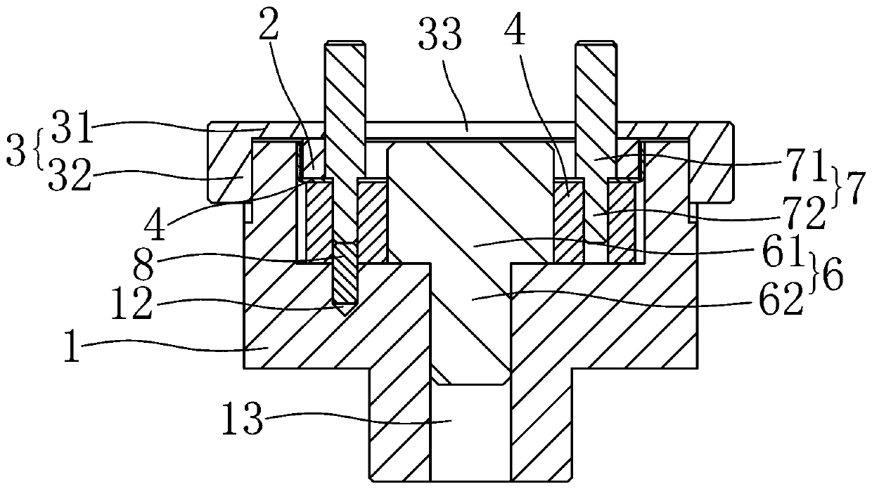
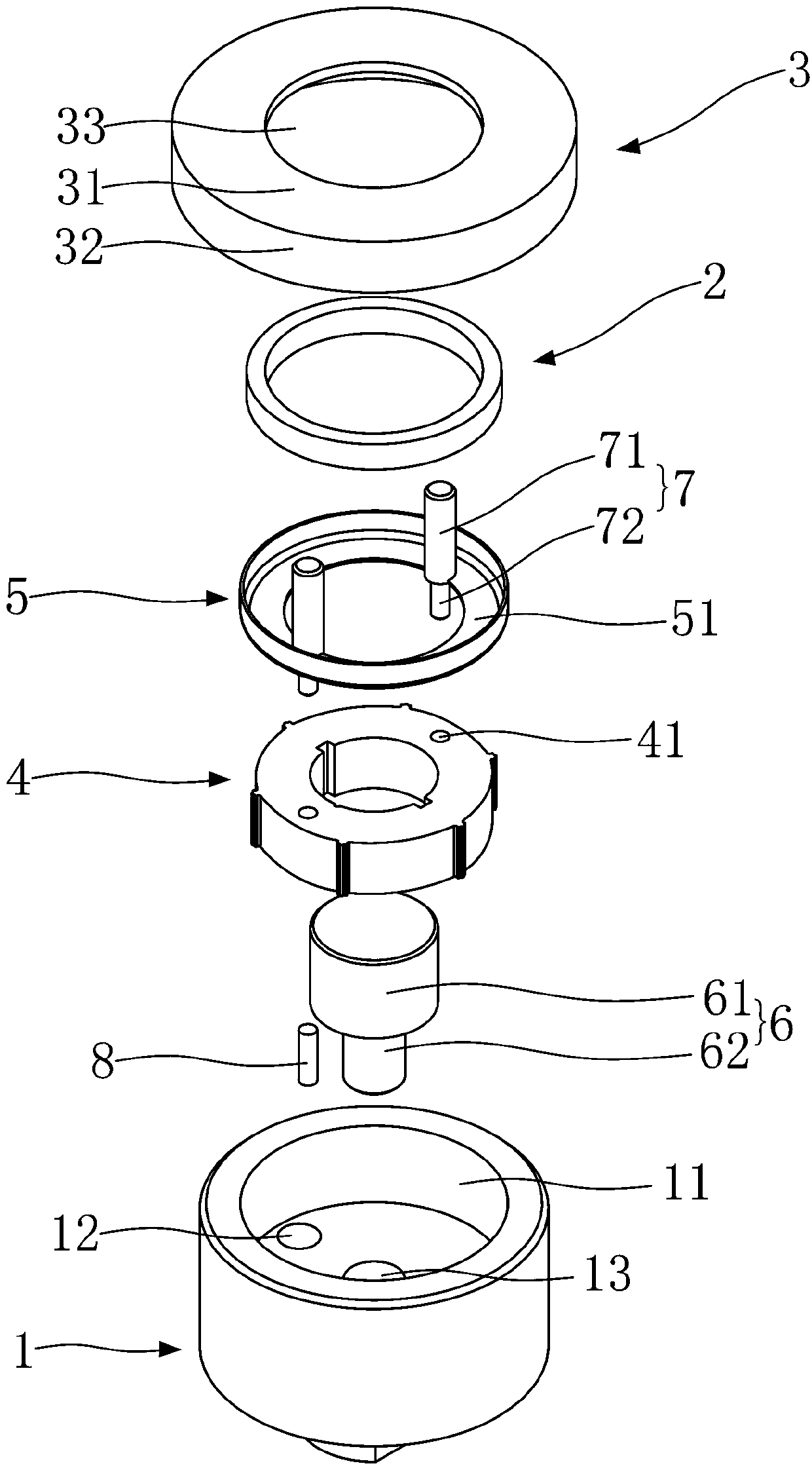
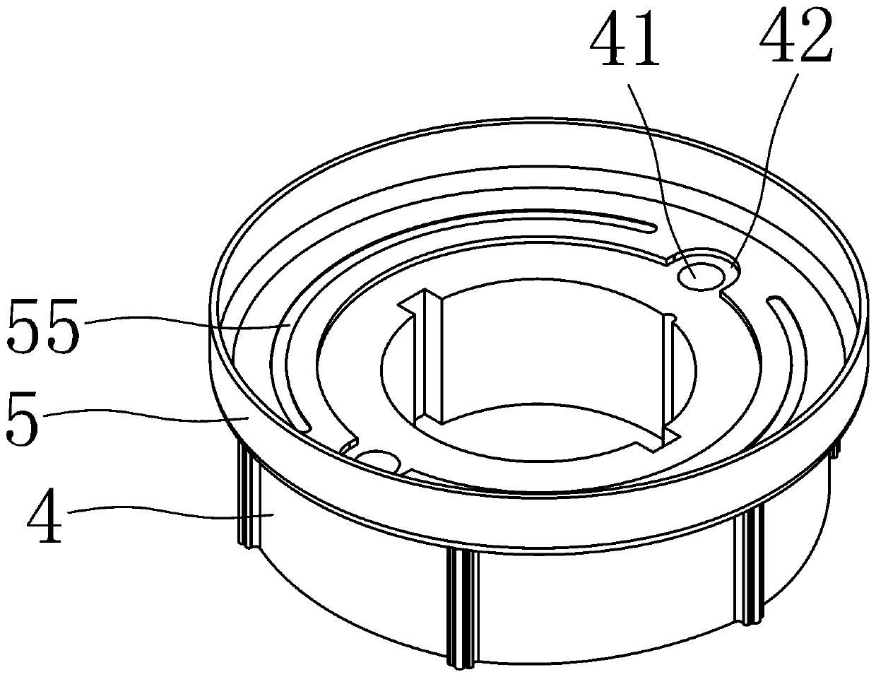
[0020] Depend on Figure 1 to Figure 3 As shown, the auxiliary device of the present invention is used for the positioning of the rotor core 4 and the end ring 5 , and for the positioning and fixing between the rotor core 4 and the end ring 5 , so as to facilitate subsequent welding to form weld marks 55 . A rotor iron core and end ring welding auxiliary device of the present invention includes a positioning sleeve 1, an annular pressure block 2, and a fixed cover 3. The positioning sleeve 1 is formed with a ring for accommodating the annular pressure block 2, the rotor core 4 and the end ring 5. The accommodation groove 11, the center of the accommodation groove 11 is provided with a positioning column 6 for positioning the circumferential position of the rotor core 4, the fixed cover 3 includes a cover top 31, and a ring-shaped fixing part 32 extend...
PUM
 Abstract
Description
Claims
Application Information
 - Generate Ideas
- Intellectual Property
- Life Sciences
- Materials
- Tech Scout
- Unparalleled Data Quality
- Higher Quality Content
- 60% Fewer Hallucinations
Browse by: Latest US Patents, China's latest patents, Technical Efficacy Thesaurus, Application Domain, Technology Topic, Popular Technical Reports.
© 2025 PatSnap. All rights reserved.Legal|Privacy policy|Modern Slavery Act Transparency Statement|Sitemap|About US| Contact US: help@patsnap.com