Stainless steel strip laser marking machine based on visual identification and positioning

A laser marking machine and visual recognition technology, applied in the field of marking, can solve the problems of inaccurate base point positioning, affecting visual inspection, and insufficient marking accuracy of steel strips, so as to avoid the impact and reduce the effect of irradiation

Active Publication Date: 2019-05-03
苏州因斯特光电技术有限公司
View PDF8 Cites 6 Cited by
  • Summary
  • Abstract
  • Description
  • Claims
  • Application Information

AI Technical Summary

Problems solved by technology

[0003] Ambient light will affect visual inspection. How to keep the light energy stable to a certain extent is an urgent problem to be solved in practical applications.
At the same time, with the refinement of product processing, factories have higher and higher requirements for product marking position accuracy; in the field of stainless steel strip marking, existing laser marking machines are often due to unreasonable design of the pressing mechanism or laser Inaccurate positioning of the base point leads to insufficient marking accuracy of the steel strip

Method used


Image

  • Stainless steel strip laser marking machine based on visual identification and positioning
  • Stainless steel strip laser marking machine based on visual identification and positioning
  • Stainless steel strip laser marking machine based on visual identification and positioning

Examples


Embodiment

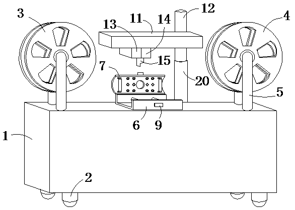
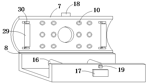
[0026] like Figure 1-5 As shown, a stainless steel strip laser marking machine based on visual recognition and positioning includes a cabinet 1 equipped with universal wheels 2, the overall device is convenient to move, and the upper side of the cabinet 1 is provided with a discharge tray 3 and a collection tray 4 , discharging and receiving respectively, the discharging tray 3 and the receiving tray 4 rotate simultaneously, the discharging tray 3 and the receiving tray 4 are fixedly installed on the cabinet 1 through the mounting frame 5, the discharging tray 3 and the receiving tray There is a fixed block 6 between the disks 4, and the fixed block 6 is fixedly connected with the upper end surface of the cabinet 1. The upper end surface of the fixed block 6 is provided with a slot, and the upper side of the fixed block 6 is horizontally provided with an arc-shaped cover 7, and one end of the arc-shaped cover 7 passes through the The rotating shaft 8 is rotatably connected wi...


PUM


Abstract

The invention belongs to the technical field of marking, and particularly relates to a stainless steel strip laser marking machine based on visual identification and positioning. The stainless steel strip laser marking machine based on visual identification and positioning comprises a machine cabinet, wherein universal wheels are installed on the machine cabinet. A material release disc and a material collection disc are arranged on the upper side of the machine cabinet and fixedly installed on the machine cabinet through installation frames. A plurality of light sources are uniformly distributed on the arc-shaped wall, close to a fixing block, of an arc-shaped cover. An installation plate is horizontally arranged on the upper side of the fixing block and installed on the machine cabinet through a lifting mechanism. A hollow cylinder is arranged on the lower sides of a marking module and a CCD visual identification module and installed on the marking module and the CCD visual identification module at the same time, and the position of the hollow cylinder corresponds to the position of a marking hole. A tight press mechanism and an adjusting mechanism are arranged in an open groovewhich is formed in the fixing block. The stainless steel strip laser marking machine based on visual identification and positioning has the advantages that the structure is reasonable, a stainless steel strip can be pressed to be flat and stable through the tight press mechanism, marking is conducted advantageously, and the influence of the ambient light on visual identification and positioning can be reduced.

Description

technical field [0001] The invention belongs to the technical field of marking, and in particular relates to a stainless steel strip laser marking machine based on visual identification and positioning. Background technique [0002] Visual inspection is to use machines instead of human eyes for measurement and judgment. Visual inspection refers to converting the captured target into an image signal through machine vision products (that is, image capture device, divided into CMOS and CCD), and sending it to a dedicated image processing system. Digitized signals; the image system performs various operations on these signals to extract the characteristics of the target, and then controls the on-site equipment actions according to the results of the discrimination. Is a valuable mechanism for production, assembly or packaging. It is invaluable in its ability to detect defects and prevent defective products from being shipped to consumers. Visual inspection has a better effect...

Claims


Application Information

Patent Timeline
Patent Type & Authority Applications(China)
IPC IPC(8): B23K26/362B23K26/70
Inventor 宁建阳
Owner 苏州因斯特光电技术有限公司
Why Eureka
Try Eureka