
Side-driving-type all-position automatic welding trolley traveling mechanism for pipeline

A technology of automatic welding and traveling mechanism, applied in welding equipment, auxiliary welding equipment, welding/cutting auxiliary equipment, etc. Guarantee the effect of normal operation

Inactive Publication Date: 2019-05-03
LUOYANG DEPING TECH
View PDF4 Cites 5 Cited by
  • Summary
  • Abstract
  • Description
  • Claims
  • Application Information

AI Technical Summary

Problems solved by technology

[0004] The purpose of the present invention is to overcome the existing welding trolley's disadvantages of reduced stability and reduced welding quality, and to provide a side-drive full-position automatic welding trolley traveling mechanism for pipelines with a new structure. The technical problem is to make it more stable and of high welding quality, so that it is more suitable for practical use

Method used


Image

  • Side-driving-type all-position automatic welding trolley traveling mechanism for pipeline
  • Side-driving-type all-position automatic welding trolley traveling mechanism for pipeline
  • Side-driving-type all-position automatic welding trolley traveling mechanism for pipeline

Examples


Embodiment Construction

[0066] In order to further explain the technical means and effects adopted by the present invention to achieve the intended purpose of the invention, in conjunction with the accompanying drawings and preferred embodiments, the traveling mechanism of a side-drive full-position automatic welding trolley for pipelines proposed according to the present invention is described below. Specific embodiments, structures, features and effects thereof are described in detail below.

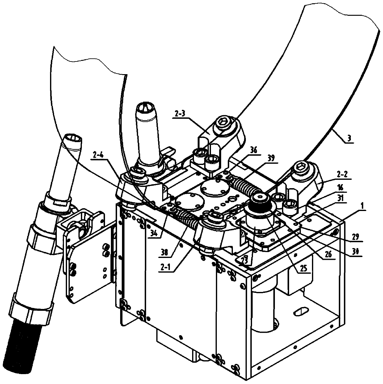
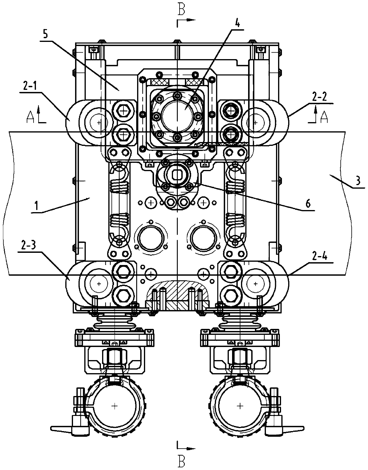
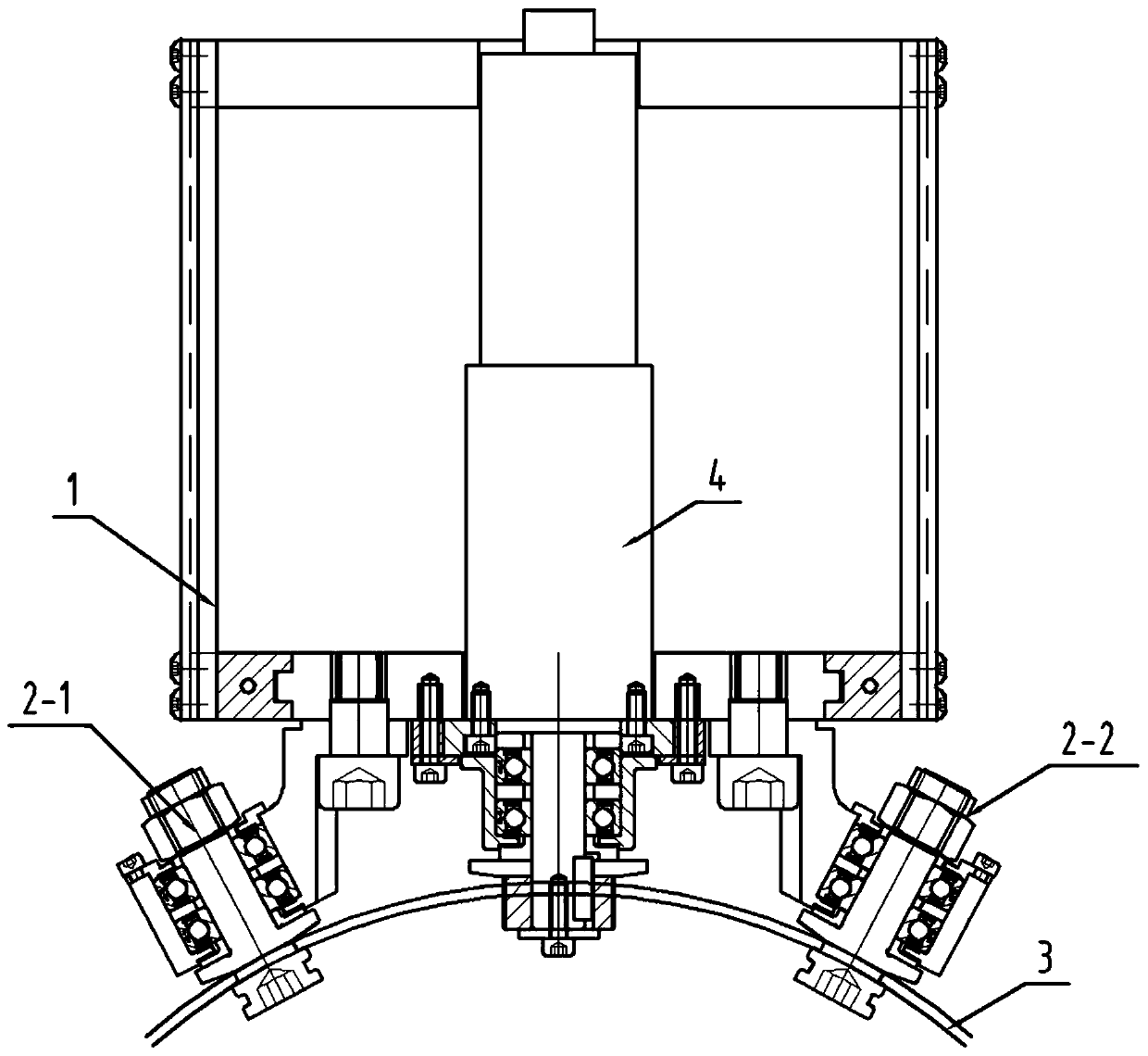
[0067] The main structure of the present invention consists of a follower assembly 2 and a double floating locking structure 4 . The double-floating locking structure makes the follower assembly close to the track 3 and has a pressing force on the track 3, so that the welding trolley is driven to walk along the track 3 by friction. Alternatively, the double-floating locking structure uses the gears to mesh with the track 3 to drive the welding trolley to walk along the track 3, and the curvature of the follow...


PUM


Abstract

The invention relates to a side-driving-type all-position automatic welding trolley traveling mechanism for a pipeline. The side-driving-type all-position automatic welding trolley traveling mechanismis constituted by four sets of following assemblies which are the same in structure, and double floating locking structures; the double floating locking structures enable the following assemblies tobe attached to and press a rail tightly, and a welding trolley is driven through friction force to travel along the rail; the double floating locking structures are constituted by driving devices, sliding locking devices and cam devices; the sliding locking devices are matched with U-shaped grooves in a box body, and thus the sliding locking devices make horizontal linear sliding on the box body;the driving devices are arranged in the sliding blocking devices, and thus the driving devices and the sliding locking devices make relative linear movement; the lower sides of the cam devices and thebox body are connected; the four sets of following assemblies can be mutually exchanged, and the machining and assembling difficulty is lowered; the declination angle of a following wheel is reduced,and as for small-pipe-diameter welding, the stability can be effectively improved; and the following wheel and a driving wheel are arranged in a floating mode, pressing force of the driving wheel forthe rail is directly adjusted by adjusting compression force of a rubber spring, normal operation of the welding trolley is ensured, and abrasion of the driving wheel to the rail is reduced.

Description

technical field [0001] The invention relates to an automatic welding trolley in the technical field of pipeline welding, in particular to a side-drive all-position automatic welding trolley traveling mechanism for pipelines. Background technique [0002] With the development of petroleum, natural gas and chemical industries, automatic welding technology has become the mainstream of pipeline construction with its unique high efficiency, high quality and reliability; at present, all-position welding mainly adopts the method of quick-installed all-position pipeline welding head and flexible track Complete, this method is mainly to meet the portability requirements of the mobile welding process; but with the decrease of the pipe diameter, the curvature of the flexible track increases, so that the deflection angle of the follower wheel of the welding trolley is too large, reducing the welding trolley. Stability, affecting welding quality. [0003] In view of the defects of the a...

Claims


Application Information

Patent Timeline
IPC IPC(8): B23K37/02
Inventor 王光临
Owner LUOYANG DEPING TECH
Learn More