
Clamping device

A fixture and bushing technology, which is applied in the manufacture of tools, grinding machines, metal processing equipment, etc., can solve problems such as low processing efficiency, waste products, and inability to meet the requirements of precision polishing

Inactive Publication Date: 2019-05-03
GUANGDONG UNIV OF TECH
View PDF6 Cites 0 Cited by
  • Summary
  • Abstract
  • Description
  • Claims
  • Application Information

AI Technical Summary

Problems solved by technology

During the operation, it is easy to cause the surface polishing degree of the polished workpiece to be inconsistent with the set parameters, resulting in waste products
Obviously, the way of manually operating polishing equipment to place mold cores to be processed is far from meeting the requirements of precision polishing, and the processing efficiency is low, which is not suitable for mass production and cannot meet the needs of production

Method used


Image

  • Clamping device
  • Clamping device
  • Clamping device

Examples


Embodiment Construction

[0026] The following will clearly and completely describe the technical solutions in the embodiments of the present invention with reference to the accompanying drawings in the embodiments of the present invention. Obviously, the described embodiments are only some, not all, embodiments of the present invention. Based on the embodiments of the present invention, all other embodiments obtained by persons of ordinary skill in the art without making creative efforts belong to the protection scope of the present invention.

[0027] In order to enable those skilled in the art to better understand the solution of the present invention, the present invention will be further described in detail below in conjunction with the accompanying drawings and specific embodiments.

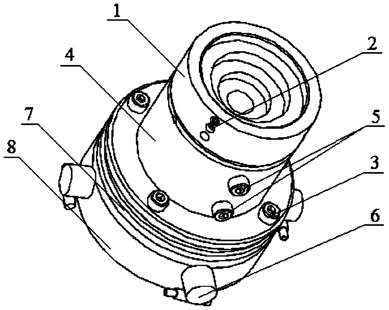
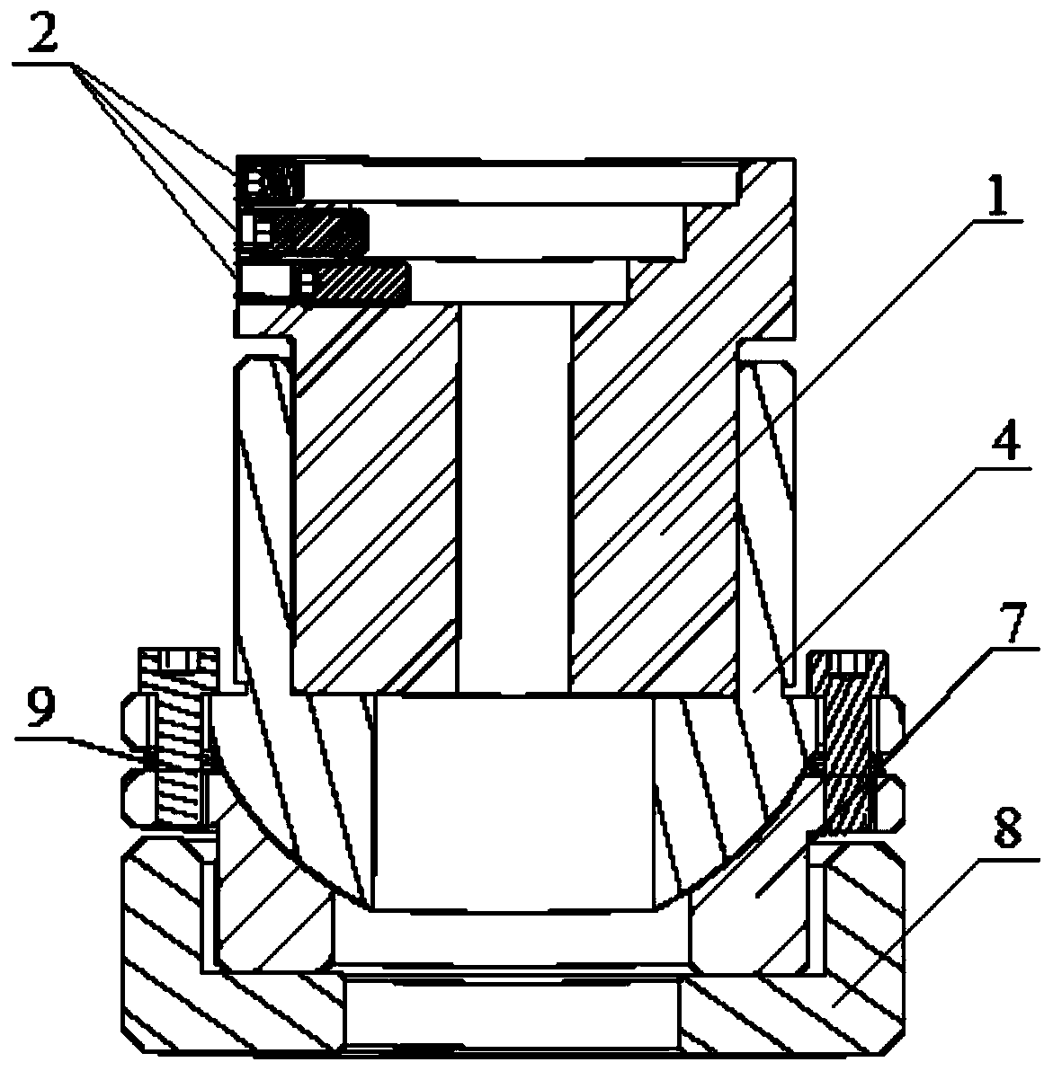
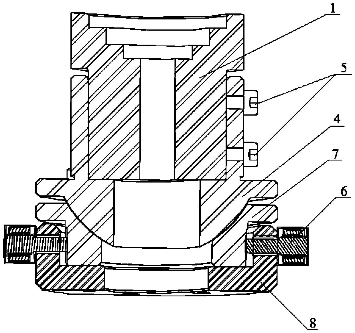
[0028] Please refer to Figure 1 to Figure 6 ,in, figure 1 Schematic diagram of the structure of the fixture provided by the embodiment of the present invention, figure 2 for figure 1 Schematic diagram of the cr...


PUM


Abstract

The invention discloses a clamping device. The clamping device includes a workpiece shaft sleeve which includes a vertical cavity provided with a plurality of limiting step surfaces to realize fixation of a workpiece, wherein a convex spherical surface shaft sleeve internally sleeves on the lower part of the workpiece shaft sleeve; a convex spherical body for fitting with the arc surface of a concave spherical surface shaft sleeve is arranged on the lower part of the convex spherical surface shaft sleeve; a base internally sleeves the concave spherical surface shaft sleeve, and coaxially rotates with a mould kernel rotary shaft; and one end of a straight bar mechanism which abuts against the side wall of the concave spherical surface shaft sleeve is arranged on the base, and then rough / tiny adjustment of workpiece axis is realized. The clamping device has the advantages that the precision is high, and degree of freedom is multiple; and multiple standard-aperture specifications of the workpiece can be fixed, position correction can be conducted while clamping is tight, the quality of a product is improved, using is convenient, and prices are low.

Description

technical field [0001] The invention relates to the technical field of polishing equipment, in particular to a clamp. Background technique [0002] At present, all kinds of optical systems play an irreplaceable role in military and civilian fields, and the increasingly prominent important role makes the optical system have higher and higher requirements for the accuracy of optical components. [0003] In the field of ultra-precision machining, polishing is the most critical process in the production and processing of optical components, and the processing effect will seriously affect the optical properties of the components. In the process of processing the mold core on the precision five-axis optical aspheric polishing machine tool, because the manual polishing operation is performed, the workpiece to be processed is adsorbed on the magnetic chuck, and the initial processing position of the machine tool is determined by the dial indicator, so that the center of the workpiec...

Claims


Application Information

Patent Timeline
Patent Type & Authority Applications(China)
IPC IPC(8): B24B13/005
Inventor 张嘉荣姚洪辉卓少木辛正旭黄松明蔡晓誉李年丰梁锐鑫朱相优邓建南
Owner GUANGDONG UNIV OF TECH
Learn More