Prime power self-rescue and walking equipment and method for an automobile under a loose and sunken road condition
A traveling equipment and motive power technology, which is applied to shunting equipment, wheel adhesion, wheels with grounded walking plate-like claws, etc. Effect
- Summary
- Abstract
- Description
- Claims
- Application Information
AI Technical Summary
Problems solved by technology
Method used
Image
Examples
Embodiment 1
[0045] Such as Figure 1-3 , 6-9 shown.
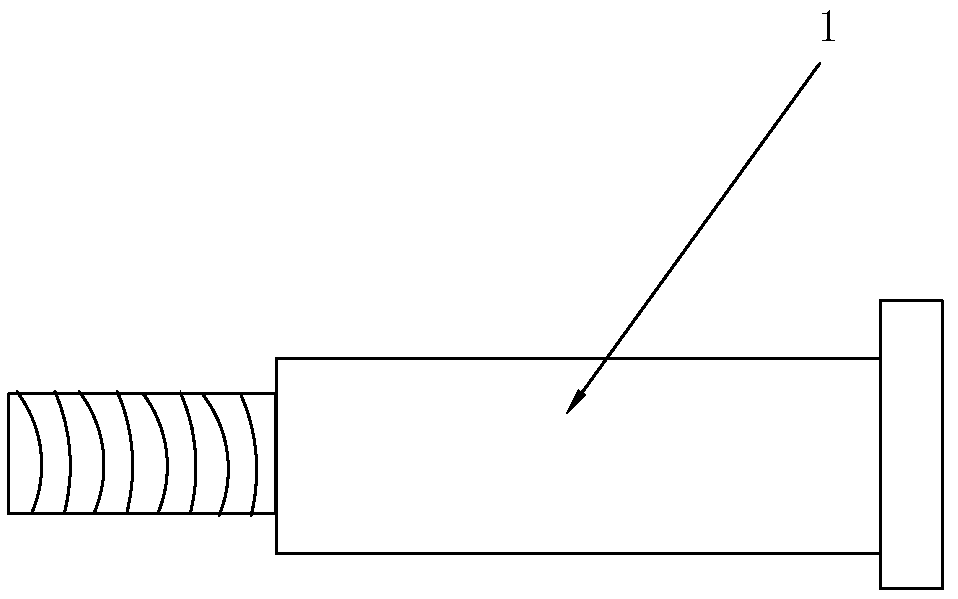
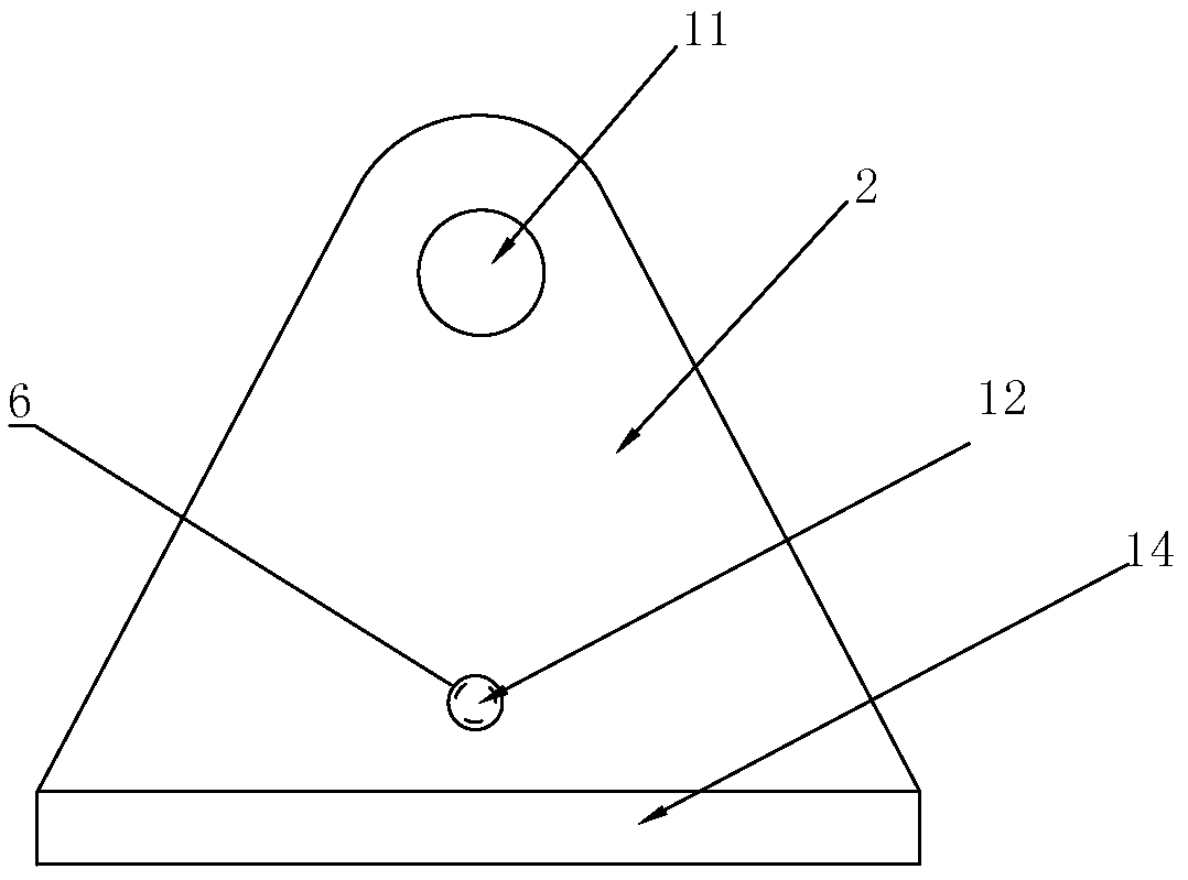
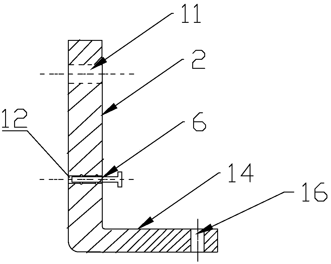
[0046]The utility model relates to a self-rescue and walking device for the driving force of an automobile in a loose road condition, which includes: an additional shaft 1, a support frame 2, a release springboard 3 and an optional additional springboard 5. The structure of the additional axis 1 is as follows figure 1 As shown, its purpose is to be screwed into the screw hole reserved on the hub 7, the strength of the additional shaft 1 can meet the actual use requirements through engineering calculation and design; the shape of the support frame 2 can be designed according to the needs, wherein preferred figure 2 Shown is a triangular plus hem configuration. The bottom limit of bracing frame 2 is provided with flanging 14, and flanging 14 can guarantee to be pressed on springboard and have bigger contact area and bigger stability, also be the base that hangs walking boots 13, as image 3 As shown, the support frame may not use fo...
Embodiment 2
[0050] Such as Figure 1-9 shown.
[0051] A driving force self-rescue and walking equipment for vehicles on loose road conditions, which includes: an additional shaft 1, a support frame 2, a breakaway springboard 3 and walking boots 13, the bottom of the walking boots 13 is provided with anti-skid patterns to improve the adhesion to the ground, the walking boots 13 sets of hanging flanges 14 positioned at the bottom of the support frame 2 ( Figure 5 ), so that the vehicle can still use the large area of the walking boots to intermittently touch the ground without sinking and keep walking in bad road conditions. The structure of the additional axis 1 is as follows figure 1 As shown, its purpose is to be screwed into the screw hole reserved on the hub 7, and the strength of the additional shaft 1 can meet the actual use requirements through engineering calculation and design; the support frame 2 ( figure 2 , 3 ) can be designed according to needs (trapezoid, rectangle, ...
Embodiment 3
[0055] The difference between this embodiment and the first and second embodiments is that the support frame 2 and the walking boot 13 are combined into one, that is, the bottom edge of the support frame 2 is lengthened and widened, so that it has the functions of both.
PUM
 Abstract
Description
Claims
Application Information
 - R&D
- Intellectual Property
- Life Sciences
- Materials
- Tech Scout
- Unparalleled Data Quality
- Higher Quality Content
- 60% Fewer Hallucinations
Browse by: Latest US Patents, China's latest patents, Technical Efficacy Thesaurus, Application Domain, Technology Topic, Popular Technical Reports.
© 2025 PatSnap. All rights reserved.Legal|Privacy policy|Modern Slavery Act Transparency Statement|Sitemap|About US| Contact US: help@patsnap.com


