

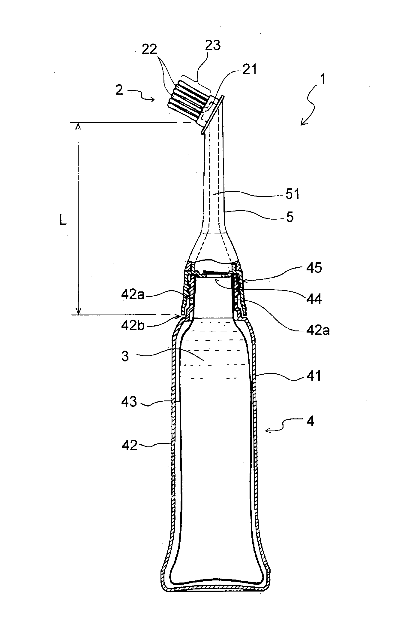
Head-hair treatment-agent applicator
a technology for treating hair and applicators, which is applied in the direction of packaging foodstuffs, packaging goods, transportation and packaging, etc., can solve the problems of difficult stably applying agents in a long tim
- Summary
- Abstract
- Description
- Claims
- Application Information
AI Technical Summary
Benefits of technology
Problems solved by technology
Method used
Image

Examples
example 1
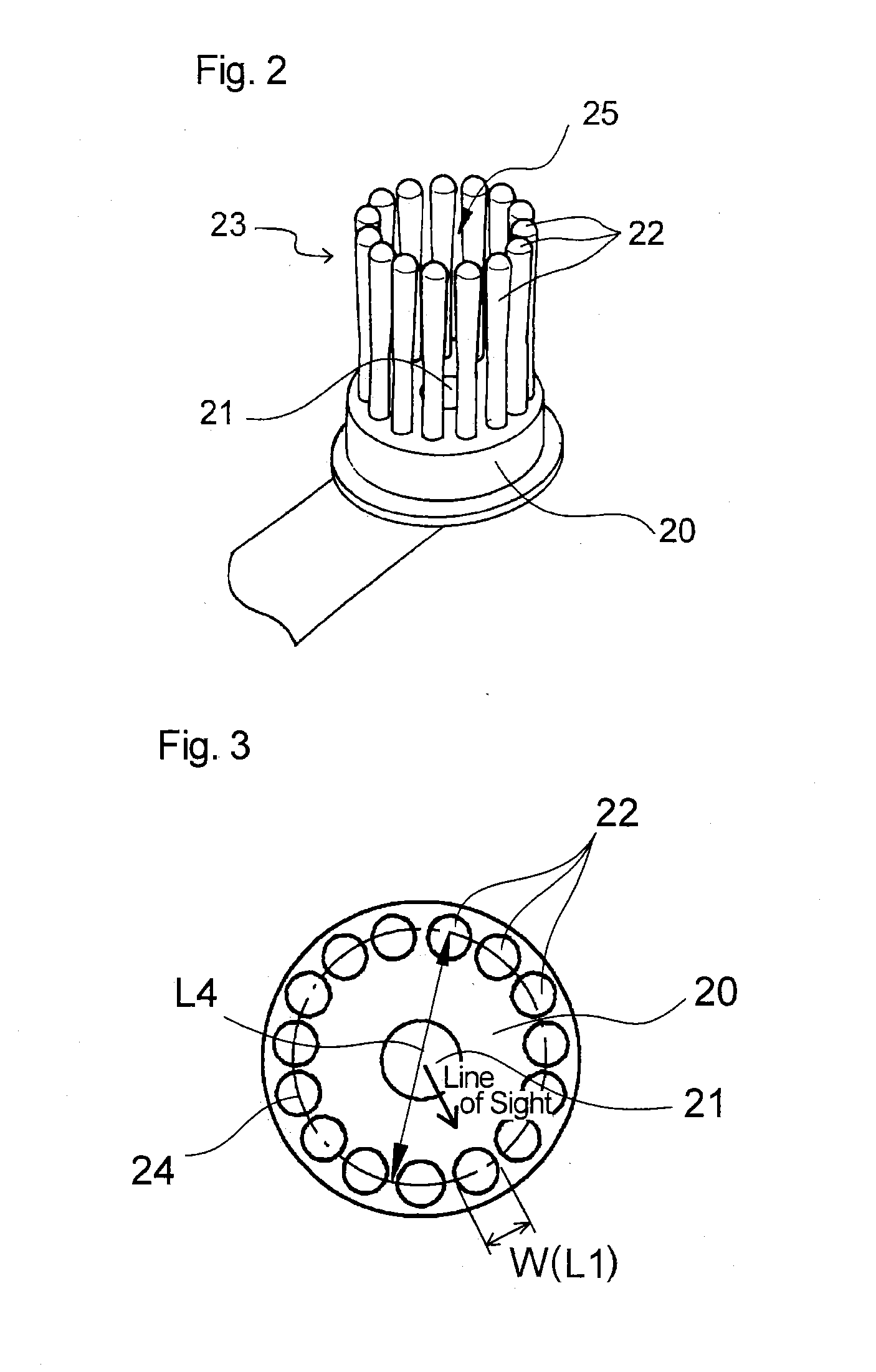
[0070]A head-hair treatment-agent applicator according to Example 1 is manufactured according to a head-hair treatment-agent applicator in modes illustrated in FIGS. 1 to 5. With Example 1, a round chamfered part (fillet part) 22i is provided to each comb tooth base end from the view point of improving the strength of the comb tooth. FIG. 11(a) illustrates the shape of the comb tooth according to Example 1. An applicator is made as a trial by a casting mold method using urethane resin.
[0071]The dimension of each part is as follows (see FIG. 5 for symbols T, T1, T2, W1 and W2, and see FIG. 3 for L4).
[0072]The height T of a comb tooth (a distance from the tip of a comb tooth to a base end 22e of the comb tooth): 16 mm
[0073]The distance T1 from the tip of the comb tooth to an upper end P1 of an inversely-tapered part: 1 mm
[0074]The distance T2 from the tip of the comb tooth to a lower end P2 of the inversely-tapered part: 9 mm
[0075]The distance from the tip of the comb tooth to an uppe...
PUM
 Abstract
Description
Claims
Application Information