Jet flow control plane for blended wing body configuration aircraft

A technology of wing-body fusion and rudder surface, applied in aircraft parts, aircraft control, aircraft transmission and other directions, can solve the problems of limited torque, increased resistance of the whole aircraft, low static stability margin of wing-body fusion layout, etc. Torque, the effect of improving control efficiency

Active Publication Date: 2019-05-03
NORTHWESTERN POLYTECHNICAL UNIV
View PDF10 Cites 5 Cited by
  • Summary
  • Abstract
  • Description
  • Claims
  • Application Information

AI Technical Summary

Problems solved by technology

Although the above-mentioned control methods are helpful to improve the nose-up moment during take-off and landing, there are still many problems: the abdominal spoiler is a rudder surface arranged on the lower surface of the fuselage. By increasing the lift in front of the center of gravity of the fuselage, the The lift force decreases, the overall lift force increases and the nose-up moment of the whole machine is increased at the same time. In its working state, the resistance of the whole machine will increase significantly, which puts extremely high requirements on the engine thrust. At the same time, the torque that can be provided is relatively limited. The combination of two surfaces meets the control requirements of the aircraft; the vertical tail stabiliz...

Method used


Image

  • Jet flow control plane for blended wing body configuration aircraft
  • Jet flow control plane for blended wing body configuration aircraft
  • Jet flow control plane for blended wing body configuration aircraft

Examples


Embodiment Construction

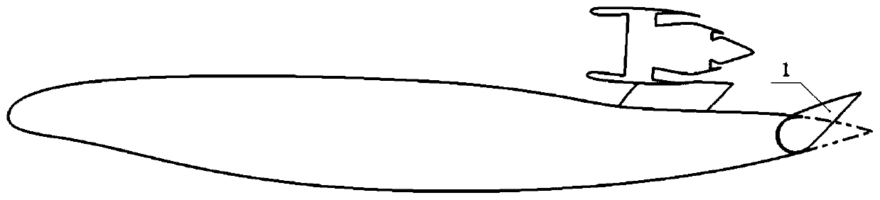
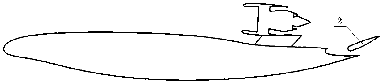
[0041] Such as Figure 9 As shown, the jet rudder surface 2 provided by the present invention is located on the rear upper surface of the wing-body fusion layout body, and under the drive of the push rod 20, slides along the arc-shaped slide rail 21 to realize the folding and unfolding of the rudder surface.

[0042] The horizontal projection of the jet rudder surface 2 in the retracted state is symmetrical with respect to the plane of symmetry 15 of the body, surrounded by four side lines, as Figure 10 Shown in the shaded area, wherein, the front portion borderline near engine 17 and the two borderlines on both sides symmetrical about the body symmetry plane 15 are straight sides, and the two borderlines on both sides are parallel to each other. The edge line at the rear portion of the jet rudder surface is an arc, and coincides with the rear edge of the body. The length L1 of the straight sides on both sides of the jet control surface=0.1L, and the L is the horizontal proj...


PUM


Abstract

The invention provides a jet flow control plane for a blended wing body configuration aircraft. The control plane is located at the back of the aircraft body, and is extended and retracted through a driving mechanism, so as to be coupled with the engine jet flow at the front of the control plane, thus improving the pitch-up moment for rising and landing of the aircraft. Compared with a traditionalblended wing body configuration tail control plane, the jet flow control plane for a blended wing body configuration aircraft has a higher control plane efficiency, and can significantly increase theavailable pitch-up moment. At the same time, since the moment arm is long, the required pitch-up moment can be achieved with a small lift loss, and the overall adverse effect on the rising and landing performance is small. The driving mechanism can be accommodated in the aircraft body, thus having no influence on the cruising performance.

Description

technical field [0001] The invention relates to the design of a longitudinal control rudder surface of an aircraft with a wing-body fusion layout, in particular to a jet flow rudder surface located at the rear of an aircraft body. Background technique [0002] Compared with the conventional layout, the wing-body fusion layout aircraft cancels the control surfaces such as the flat tail. Due to the flat lift body design, the smooth transition between the fuselage and the wings greatly reduces the overall wetted area and reduces the drag. The aerodynamic efficiency is significantly improved, which is one of the research hotspots in the future aircraft layout. [0003] One of the main challenges in the design of aircraft with integrated wing-body layout is the lack of longitudinal control capability caused by the cancellation of the horizontal tail, especially when taking off and landing at low speeds, the trim pressure of nose-down moment is relatively high, often accompanied b...

Claims


Application Information

Patent Timeline
IPC IPC(8): B64C9/00B64C13/36
Inventor 辛振庆张彬乾李栋陈真利顾文婷王刚张明辉袁昌盛张永杰桑为民张怡哲李杰
Owner NORTHWESTERN POLYTECHNICAL UNIV
Why Eureka
Try Eureka