
Cloth feeding mechanism of embroidery machine and embroidery machine

A technology of cloth feeding mechanism and embroidery machine, which is applied to the mechanism of embroidery machines, embroidery machines, textiles and papermaking, etc. It can solve the problems of cloth wrinkles, unfavorable embroidery machine embroidery, and the inability of effective smoothing and equalization of cloth, and achieve the goal of increasing tension. Effect

Inactive Publication Date: 2019-05-03
尹小美
View PDF7 Cites 1 Cited by
  • Summary
  • Abstract
  • Description
  • Claims
  • Application Information

AI Technical Summary

Problems solved by technology

[0003] The cloth feeding mechanism is a device used to send the cloth to the embroidery machine for embroidery, but in the process of feeding the cloth to the embroidery machine in the existing cloth feeding mechanism, the cloth cannot be smoothed out effectively, causing wrinkles in the cloth, which is not conducive to the embroidery machine. embroidered

Method used


Image

  • Cloth feeding mechanism of embroidery machine and embroidery machine
  • Cloth feeding mechanism of embroidery machine and embroidery machine
  • Cloth feeding mechanism of embroidery machine and embroidery machine

Examples


Embodiment 1

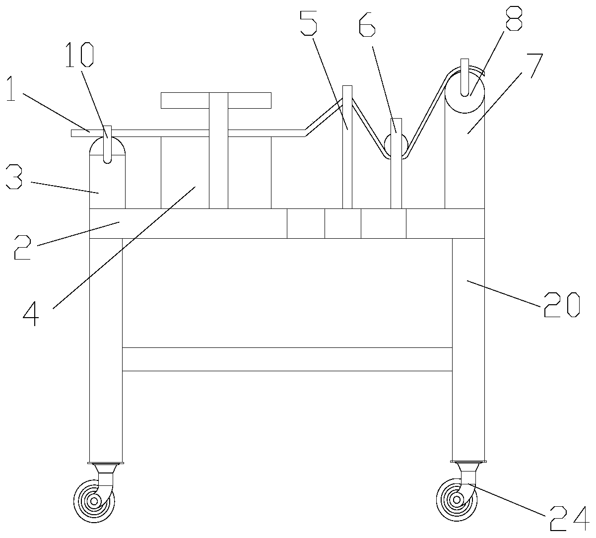
[0027] like Figure 1-3As shown, a cloth feeding mechanism of an embroidery machine includes a support plate 2 on which a first fixed column 3, a smoothing box 4, a support plate 5, a second fixed column 6 and a third fixed column are arranged. 7. The first fixed column 3, the second fixed column 6 and the third fixed column 7 are respectively located on both sides of the support plate 2, and the first fixed column 3, the second fixed column 6 and the third fixed column 7 are all in the form of Symmetrically distributed, the first fixed column 3, the second fixed column 6 and the third fixed column 7 are fixedly connected to the support plate 2, the first fixed column 3, the second fixed column 6 and the third fixed column 7 A paper roll 8 is arranged between them, and the first fixed column 3, the second fixed column 6 and the third fixed column 7 are all rotatably connected with the paper roll 8 on each of them, and the support plate 2 is provided with a cloth 1 Paired thro...

Embodiment 2

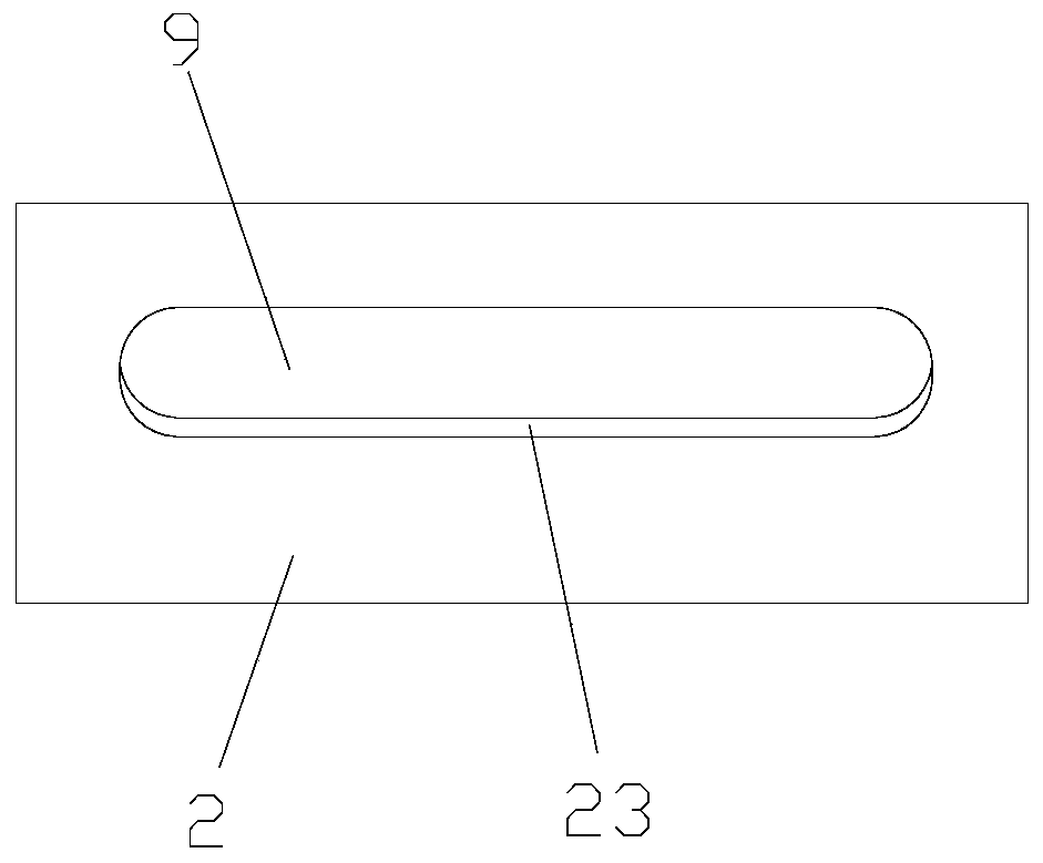
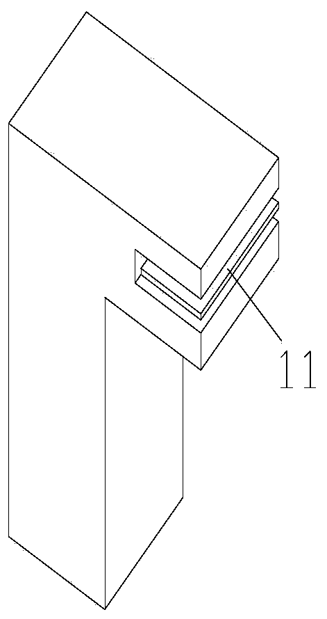
[0030] like Figure 1-6 As shown, a cloth feeding mechanism of an embroidery machine includes a support plate 2 on which a first fixed column 3, a smoothing box 4, a support plate 5, a second fixed column 6 and a third fixed column are arranged. 7. The first fixed column 3, the second fixed column 6 and the third fixed column 7 are respectively located on both sides of the support plate 2, and the first fixed column 3, the second fixed column 6 and the third fixed column 7 are all in the form of Symmetrically distributed, the first fixed column 3, the second fixed column 6 and the third fixed column 7 are fixedly connected to the support plate 2, the first fixed column 3, the second fixed column 6 and the third fixed column 7 A paper roll 8 is arranged between them, and the first fixed column 3, the second fixed column 6 and the third fixed column 7 are all rotatably connected with the paper roll 8 on each of them, and the support plate 2 is provided with a cloth 1 Paired thr...


PUM


Abstract

The invention discloses a cloth feeding mechanism of an embroidery machine and the embroidery machine. The cloth feeding mechanism comprises a supporting plate, the supporting plate is provided with first fixed pillars, a leveling box, a supporting pillar, second fixed pillars and third fixed pillars, and the first fixed pillars, the second fixed pillars and the third fixed pillars are located atthe two sides of the supporting plate respectively, and symmetrically distributed; the first fixed pillars, the second fixed pillars and the third fixed pillars are fixedly connected with the supporting plate, winding rolls are arranged among the first fixed pillars, the second fixed pillars and the third fixed pillars, the first fixed pillars, the second fixed pillars and the third fixed pillarsare rotatably connected with the winding rolls on the respective first fixed pillars, the second fixed pillars and the third fixed pillars, the supporting plate is provided with a penetrating groove matched with cloth, cloth clamping devices are arranged on the fixed fixed pillars and the third fixed pillars, clamping plates are arranged on the cloth clamping devices, and springs are arranged on the clamping plates. By means of the cloth feeding mechanism of the embroidery machine, cloth can be effectively leveled.

Description

technical field [0001] The invention relates to a cloth feeding mechanism of an embroidery machine and the embroidery machine. Background technique [0002] Embroidery machines, embroidery machines, or embroidery machines. When embroidery just started to break away from manual embroidery, the so-called embroidery machine at that time was not a real embroidery machine, because the embroidery machine at that time used a traditional sewing machine, replaced with a bottom plate with a small round hole, and the sewing machine needle kept going. Going in and out up and down, and moving back and forth with the taut cloth in the embroidery frame, in fact, this so-called embroidery machine is still a kind of hand embroidery. [0003] The cloth feeding mechanism is a device used to send the cloth to the embroidery machine for embroidery, but in the process of feeding the cloth to the embroidery machine in the existing cloth feeding mechanism, the cloth cannot be smoothed out effectiv...

Claims


Application Information

Patent Timeline
Patent Type & Authority Applications(China)
IPC IPC(8): D05C9/00D05C13/00D06C15/00
Inventor 不公告发明人
Owner 尹小美
Learn More