
Mining excavator working mechanism and mining excavator

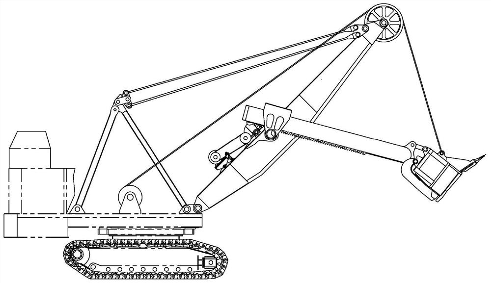
A working mechanism and excavator technology, which is applied in the direction of mechanically driven excavators/dredgers, etc., can solve the problems of increased manufacturing cost, larger matching clearance, and affecting the service life of the pushing mechanism.

Active Publication Date: 2021-04-20
TAIYUAN HEAVY IND
View PDF6 Cites 0 Cited by
  • Summary
  • Abstract
  • Description
  • Claims
  • Application Information

AI Technical Summary

Problems solved by technology

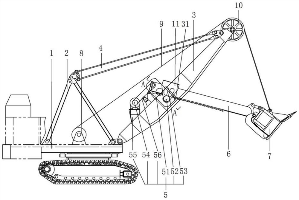
When the excavator is working, the boom box will be deformed under the action of composite forces such as bending, torsion, etc., which will lead to the deterioration of the transmission meshing state of the pushing reducer. Therefore, in order to slow down the deformation of the boom to control the pushing Due to the deformation of the lower box of the reducer, the existing boom is designed to meet the requirements of stiffness, resulting in a large weight of the boom, which increases the manufacturing cost; at the same time, the pushing shaft in the pushing mechanism cooperates with the boom After being used for a period of time, the sliding bearing at the place will wear out, which will increase the fit gap, resulting in the deterioration of the transmission meshing state between the pushing shaft and the pushing reducer, which will seriously affect the service life of the pushing mechanism
As the weight of the boom increases, the overall weight of the excavator also increases, resulting in an increase in the overall useless work of the excavator and a decrease in the performance of the entire machine

Method used


Image

  • Mining excavator working mechanism and mining excavator
  • Mining excavator working mechanism and mining excavator
  • Mining excavator working mechanism and mining excavator

Examples


Embodiment Construction

[0026] In order to make the objectives, technical solutions and advantages of the present invention clearer, the technical solutions of the present invention will be clearly and completely described below with reference to the specific embodiments of the present invention and the corresponding drawings. Obviously, the described embodiments are only some, but not all, embodiments of the present invention. Based on the embodiments of the present invention, all other embodiments obtained by those of ordinary skill in the art without creative work fall within the protection scope of the present invention.

[0027] The technical solutions provided by the embodiments of the present invention are described in detail below with reference to the accompanying drawings.

[0028] as attached figure 1 As shown, the exemplary mining excavator working mechanism includes a working platform, an A-frame, a boom, a stick, a bucket, a pushing mechanism, a hoisting mechanism, a guy rope and a hoi...


PUM


Abstract

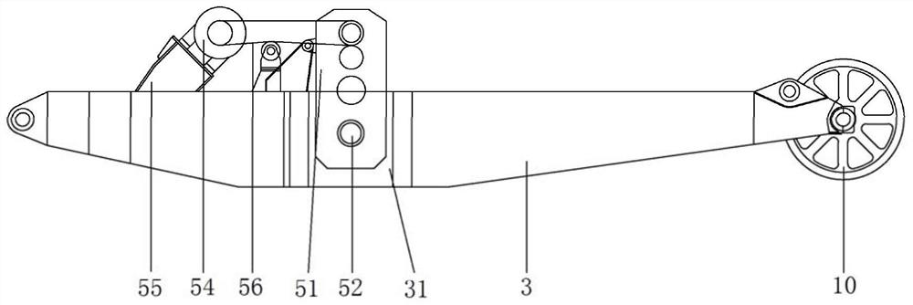
The invention discloses a mining excavator working mechanism. The working mechanism includes a working platform, an A-frame, a boom, a stay rope, a pushing mechanism, a stick, a bucket, a lifting mechanism and a lifting wire rope; the pushing mechanism includes a pushing reducer, a pushing shaft and a pushing gear, There are two box girders in the middle of the jib. The two box girders are arranged on both sides of the middle. There is a gap space between the two box girders. The thrust reducer is a hollow shaft reducer, the push reducer is set on the neutral space, and the push shaft passes through one of the two bearing through holes, the hollow shaft hole of the push reducer and the two the other of the two bearing through holes. The working mechanism of the mining excavator of the present invention is provided with a gap space on the boom, and the push reducer is installed on the gap space of the boom by using the push shaft, so as to separate the push reducer from the boom , It can avoid the deformation of the boom from affecting the pushing reducer.

Description

technical field [0001] The invention relates to the technical field of mining excavators, in particular to a mining excavator working mechanism and a mining excavator. Background technique [0002] Mechanical shovel excavator, also known as mining excavator, is a special equipment used for open-pit mining. The working mechanism of the excavator mainly includes a working platform, A-frame, boom, stick, shovel Bucket, pushing mechanism, lifting mechanism, tension rope and lifting wire rope, etc. The root of the boom is hinged at the front end of the upper platform, and the fixed length of the rope connects the head of the boom with the A-frame on the platform to pull the inclined boom, and the head of the boom is equipped with a pulley , which is used to provide the reversal of the hoisting wire rope. When the excavator is working, the bucket completes the excavation of the material under the combined action of the lifting force of the lifting wire rope and the thrust of the...

Claims


Application Information

Patent Timeline
IPC IPC(8): E02F3/48E02F3/52
Inventor 司建明赵腾云李光
Owner TAIYUAN HEAVY IND
Learn More