High-altitude tightening device for Dyneema rope

A high-voltage, main-body technology, applied in the direction of overhead lines/cable equipment, etc., can solve problems such as difficult control, safety and reliability judged only by experience, inconvenient transition, etc., and achieve tightening speed that is easy to adjust, easy to maintain and Good effect of upgrade and fretting performance

Pending Publication Date: 2019-05-03
STATE GRID CORP OF CHINA +2
View PDF0 Cites 2 Cited by
  • Summary
  • Abstract
  • Description
  • Claims
  • Application Information

AI Technical Summary

Problems solved by technology

[0003] Dinima rope is made of Dinima high-strength polyethylene fiber, and then uses the wire body strengthening process to make an ultra-smooth rope body. Its surface hardness is low and easy to compress. Unable to apply sag adjustment of Dyneema rope
At present, the temporary anchorage of the tension pay-off Dyneema guide rope, the sag adjustment and the secondary protection of the Dyneema load-carrying cable across the closed net only use short Dyneema rope sleeves and saddle chucks to clamp the Dyneema rope. method, safety and reliability can only be judged by experience, it is extremely inconvenient to install and disassemble at high altitude, there are certain safety hazards, and the degree of safety risk is high
Up to now, the main way to solve this problem is to manually adjust by mechanical winches (hoists) or lever hoists combined with anchor rope devices. It is not very convenient to transition in the terrain environment, and the effect of slowly tightening the Dyneema rope by the lever hoist combined with the anchor rope device is not ideal, the work efficiency is low, and there are many types and quantities of tools and equipment, and there are certain safety hazards

Method used


Image

  • High-altitude tightening device for Dyneema rope
  • High-altitude tightening device for Dyneema rope
  • High-altitude tightening device for Dyneema rope

Examples


Embodiment Construction

[0021] The present invention will be further described below in conjunction with the accompanying drawings. The following examples are only used to illustrate the technical solution of the present invention more clearly, but not to limit the protection scope of the present invention.

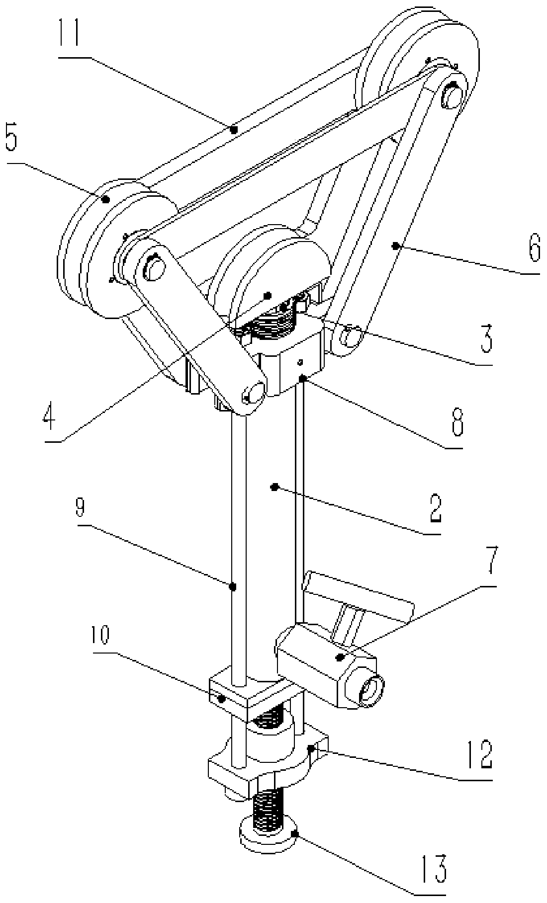
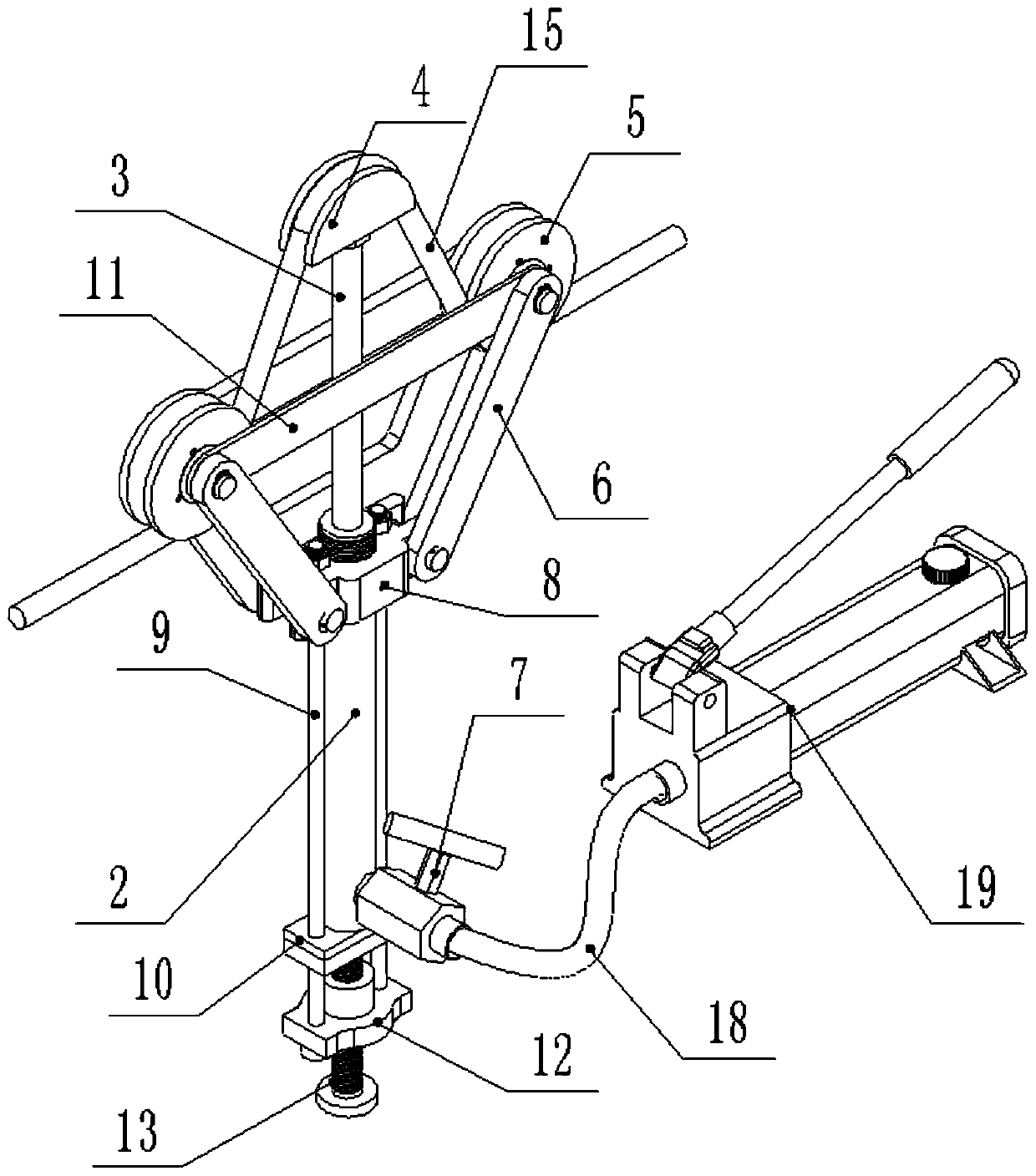
[0022] Such as figure 1 As shown, the Dyneema rope high-altitude tightening device includes a main body support frame, two sets of rollers 5 are respectively connected to both sides of the main body support frame, and the rollers 5 are detachably connected to the main body support frame. The telescoping end of the mechanism is connected with a propulsion wheel 4, and the propulsion wheel 4 moves up and down between two groups of rollers 5.

[0023] The telescoping mechanism is preferably a high-pressure oil cylinder 2, which provides power for the device. The top end of the piston rod 3 of the high-pressure oil cylinder 2 is connected with the propulsion wheel 4; the small-volume high-pressure...


PUM


Abstract

The invention discloses a high-altitude tightening device for a Dyneema rope, and the device comprises a main body supporting frame. Two sets of rolling wheels are respectively connected to the two sides of the main body supporting frame, and a telescopic mechanism is arranged in the main body supporting frame. A telescopic end of the telescopic mechanism is connected with a pushing wheel, and thepushing wheel moves up and down between the two sets of rolling wheels. The telescopic mechanism drives the pushing wheel to move up and down, so the manpower is saved. The pushing wheel and the rolling wheels cooperate with each other to enable the Dyneema rope to freely roll between the rolling wheels, thereby reducing mechanical damages to the Dyneema rope while effective tightening is achieved, and enabling the tightening to be smooth and effective. The small-size telescopic mechanism is adopted, so the micro-motion performance is good, and operation is convenient. The split type structure is good in detachability and convenient to maintain and upgrade.

Description

technical field [0001] The invention belongs to the technical field of power transmission line stringing construction, and in particular relates to a high-altitude tightening device for a Dyneema rope. Background technique [0002] At present, Dyneema rope is widely used in the construction process of power transmission lines due to its advantages of high strength, good insulation performance, small diameter, light weight, easy to carry and operate. When the Dyneema rope is used as the main load-bearing cable across the high-speed rail, high-voltage power line, and expressway line sealing protection facilities, the Dyneema rope usually has a long service life, often lasting for several days or even ten days. When there is rain, snow and fog during the spanning construction period, the self-weight of the load-bearing cable and the network body of the sealing network will increase, and the sag will increase, which will lead to insufficient minimum safe distance between the loa...

Claims


Application Information

Patent Timeline
IPC IPC(8): H02G1/04
Inventor 马龙赵冬徐扬
Owner STATE GRID CORP OF CHINA
Why Eureka
Try Eureka