Bus duct structure

A technology of busway and dovetail groove, which is applied in the direction of cooling busbar device and fully enclosed busbar device, which can solve the problems of inconvenient use, small heat dissipation area of ​​conductor and shell, and unfavorable heat dissipation

Pending Publication Date: 2019-05-03
WETOWN ELECTRIC GRP CO LTD
View PDF0 Cites 3 Cited by
  • Summary
  • Abstract
  • Description
  • Claims
  • Application Information

AI Technical Summary

Problems solved by technology

[0002] Various bus ducts are often used in power transmission and distribution in the power supply system. The existing bus ducts generally include the shell and the multi-phase conductors covered by insulating materials in the shell. The existing bus ducts This kind of busway structure, because the conductor is completely covered by insulating material, the heat dissipation area between the conductor and the shell is small, which is not conducive to the overall heat dissipation during use, and the heat dissipation performance is poor. In addition, the shell of the busway and the conductor The overall design makes it troublesome to install, the conductive connection is unreliable, and the manufacturing cost is also high. When the conductor needs to be connected to the outside, the plug box and the bus duct have poor adaptability, so it is difficult to directly connect the conductor to the outside, which is very inconvenient to use

Method used


Image

  • Bus duct structure
  • Bus duct structure
  • Bus duct structure

Examples


Embodiment Construction

[0014] The busway structure of the present invention will be described in further detail below in conjunction with the accompanying drawings and specific embodiments.

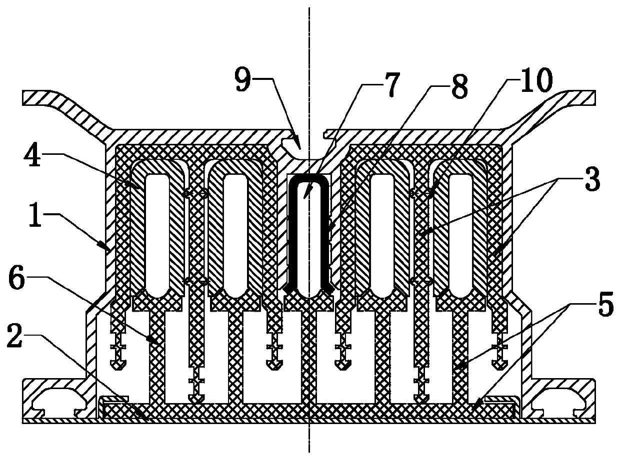
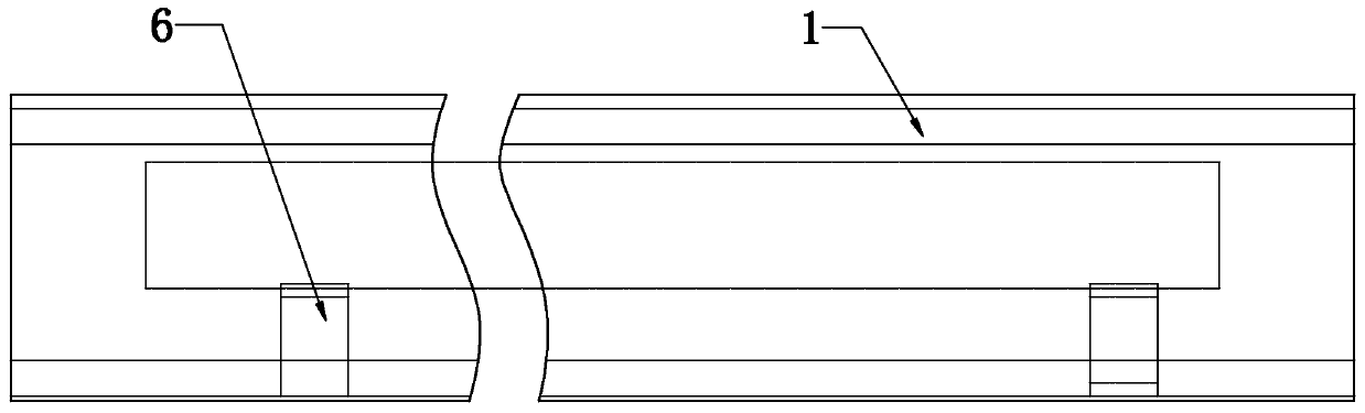
[0015] As shown in the figure, the busway structure of the present invention includes a shell 1 with an opening at the bottom and a cover plate 2 installed at the bottom opening of the shell, that is to say, the shell is composed of a frame surrounded by two sides and a top surface, The middle part of the housing 1 has a U-shaped slot 7 formed by two plates extending from the top to the bottom of the cavity. A grounding conductor 8 is placed in the U-shaped slot 7. The U-shaped slot 7 separates the inner cavity of the housing 1 from the The middle part is divided into two placement cavities on the left and right, and an m-shaped insulator 3 is placed in the left and right cavities, and each insulator 3 forms two U-shaped placement grooves for U-shaped conductors 4 respectively. The conductor 4 is separated from...


PUM


Abstract

The invention discloses a bus duct structure, which comprises a shell with an opening formed in the bottom of the shell, and a cover plate mounted at the opening in the bottom of the shell. An inner cavity of the shell is divided into a left containing cavity and a right containing cavity from the middle. The left cavity and the right cavity are each internally provided with an m-shaped insulatingpart. Each insulating part is provided with two U-shaped containing grooves used for containing U-shaped conductors. A plurality of insulating supports distributed in the longitudinal direction of the shell are installed on the cover plate. Each insulating support is provided with supporting arm used for being supported at the lower end of the corresponding phase of a conductor. With the adoptionof the above structure, all conductors are in large-area contact with the shell or the shell at the part of a ground wire, so that the heat dissipation performance is improved. In addition, due to the arrangement of a protruding structure, the stable stress is guaranteed. The connection reliability is improved. Meanwhile, the bus duct is reasonable in overall structural design, easy in connectionand installation, convenient in insertion and connection and very high in conductive reliability.

Description

technical field [0001] The invention relates to a component for power transmission and distribution in a power supply system, in particular to a bus duct structure. Background technique [0002] Various bus ducts are often used in power transmission and distribution in the power supply system. The existing bus ducts generally include the shell and the multi-phase conductors covered by insulating materials in the shell. The existing bus ducts This kind of busway structure, because the conductor is completely covered by insulating material, the heat dissipation area between the conductor and the shell is small, which is not conducive to the overall heat dissipation during use, and the heat dissipation performance is poor. In addition, the shell of the busway and the conductor The integrated design makes installation troublesome, the conductive connection is unreliable, and the manufacturing cost is also high. When the conductor needs to be connected to the outside, the plug bo...

Claims


Application Information

Patent Timeline
IPC IPC(8): H02G5/06H02G5/10
Inventor 王署斌
Owner WETOWN ELECTRIC GRP CO LTD
Why Eureka
Try Eureka