
A milling tool for flange bearing parts

A flange bearing and tooling technology, which is applied to metal processing equipment, metal processing machinery parts, supports, etc., can solve the problems of difficult positioning and clamping methods, low efficiency, poor drilling quality of parts, and achieve positioning Fixing is convenient and efficient, avoiding damage and ensuring the quality of milling processing

Active Publication Date: 2021-03-30
CHENGDU AIRCRAFT INDUSTRY GROUP
View PDF5 Cites 0 Cited by
  • Summary
  • Abstract
  • Description
  • Claims
  • Application Information

AI Technical Summary

Problems solved by technology

[0005] The object of the present invention is to provide a face milling device for flange bearing parts, in view of the large deformation of the existing flange bearing face milling structure, difficult positioning and clamping methods, fewer processing parts, and smaller batches. Large size, low efficiency, and poor surface quality of parts and poor drilling quality in the process of processing. Provide a positioning and fixing tool for single positioning and clamping of flange bearing parts to achieve precise milling of parts

Method used


Image

  • A milling tool for flange bearing parts
  • A milling tool for flange bearing parts
  • A milling tool for flange bearing parts

Examples


Embodiment 1

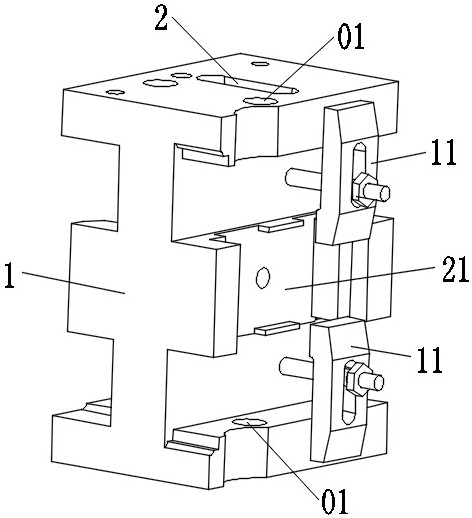
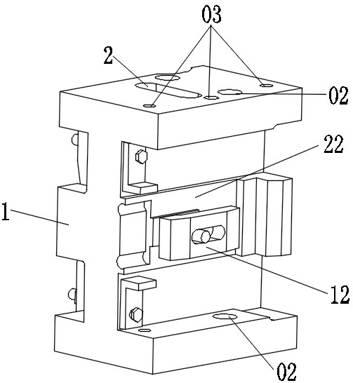
[0037] A kind of milling tool for the flange bearing parts of this embodiment, such as figure 1 with figure 2 As shown, it includes an I-shaped tooling base 1 with a pressing part 2 on one side, the upper and lower ends of the front of the tooling base 1 are symmetrically provided with first main body positioning holes 01, and the front of the tooling base 1 is provided with a first The positioning part 21, the upper and lower sides of the first positioning part 21 are symmetrically provided with the first clamping part 11; the upper and lower ends of the back of the tooling base 1 are symmetrically provided with the second main body positioning hole 02, and the tooling base 1 is provided with a second positioning part 22 on the back, and the second clamping part 12 is provided on the second positioning part 22; the upper end of the back of the tooling base 1 is also provided with a number of drill guide holes 03.

[0038] The overall structure of the tooling base 1 is I-sha...

Embodiment 2

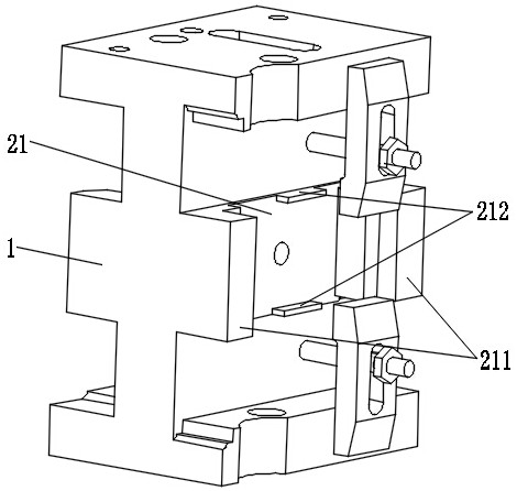
[0043] This embodiment is further optimized on the basis of embodiment 1, such as image 3 As shown, it also includes a first auxiliary support part 211 and a tool positioning part 212, the first auxiliary support part 211 is arranged on the left and right ends of the first positioning part 21, and the tool positioning part 212 is symmetrically arranged on the first positioning part 21 upper and lower sides.

[0044] The first positioning part 21 performs positioning and fixing on the flange bearing part on the plane, and the left and right ends of the first positioning part 21 respectively correspond to the left positioning surface and the right positioning surface of the flange bearing part and are provided with a first auxiliary support part 211 , that is, through the matching and bonding of the first auxiliary support parts 211 at the left and right ends and the positioning surfaces on the left and right sides of the flange bearing part, the quick positioning and fixing of...

Embodiment 3

[0047] This embodiment is further optimized on the basis of above-mentioned embodiment 1 or 2, such as Figure 4 As shown, a second auxiliary support portion 221 is also included, and the second auxiliary support portion 221 is disposed at the left end or the right end of the second positioning portion 22 .

[0048] The second auxiliary support part 221 is arranged on the left end or the right end of the second positioning part 22, and the second auxiliary support part 221 is arranged on the positioning surface of the left side or the right side of the corresponding flange bearing part, through the second auxiliary support part 221 and the convex The matching and fitting between the positioning surfaces on the left or right side of the flange bearing part can realize the quick positioning of the flange bearing part in the left and right directions on the back of the tooling base 1 .

[0049] Other parts of this embodiment are the same as those of Embodiment 1 or 2 above, so de...


PUM


Abstract

The invention discloses a surface milling machining tool for a flange bearing part, and belongs to the technical field of part positioning fixed tools. The surface milling machining tool includes a tool base, a compressing part is arranged on one side of the tool base, first main body locating holes are symmetrically formed in the upper end and the lower end of the front surface of the tool base,a first positioning part is arranged on the front surface of the tool base, and first clamping parts are symmetrically arranged on the upper side and the lower side of the first positioning part; second main body positioning holes are symmetrically formed in the upper end and the lower end of the back surface of the tool base, a second positioning part is arranged on the back surface of the tool base, and a second clamping part is arranged on the second positioning part; and a plurality of drill head guiding holes are further formed in the upper end of the back surface of the tool base. The surface milling machining tool for the flange bearing part has the beneficial effects that positioning and fixing of the flange bearing part are simple, convenient and efficient, machining quality of asurface milling is effectively guaranteed, coaxiality of the hole structure on the flange bearing part is effectively guaranteed, and damage on the edge strip of the flange bearing part is avoided.

Description

technical field [0001] The invention belongs to the technical field of part positioning and fixing tooling, and in particular relates to a milling tool for flange bearing parts. Background technique [0002] With the increase of foreign subcontracting projects, the number of small and medium-sized die forging and casting parts of foreign civil aircraft continues to increase, and the digital processing efficiency of die forging and casting parts has been significantly improved. However, due to the lack of processing experience in die forging and casting parts, aviation manufacturing units have low processing efficiency and low processing quality for such parts. Therefore, it is imminent to solve the processing efficiency of such parts and rapidly improve the processing quality of parts. At present, the number of small and medium-sized die forging and casting parts in aviation manufacturing units continues to increase. During the processing of casting flange bearing parts, du...

Claims


Application Information

Patent Timeline
Patent Type & Authority Patents(China)
IPC IPC(8): B23Q3/06
Inventor 俞鸿均江波彭彩霞罗志勇李先健何莲
Owner CHENGDU AIRCRAFT INDUSTRY GROUP
Learn More