Leg-type combined buffer for recoverable rocket landing mechanism

A buffer, leg-type technology, applied in the aerospace field, can solve the problems of low impact energy and inability to meet the rocket landing recovery, etc., to achieve stable impact force, good buffering energy absorption effect, and improving energy effect.

Active Publication Date: 2019-05-07
HARBIN INST OF TECH
View PDF6 Cites 2 Cited by
  • Summary
  • Abstract
  • Description
  • Claims
  • Application Information

AI Technical Summary

Problems solved by technology

[0005] In order to solve the problem that the existing landing buffer mechanism only uses a metal honeycomb structure as the buffer material, the impact energy absorbed per unit volume is low and cannot meet the requirements of rocket landing recovery, and further provides a recyclable rocket landing mechanism leg-combined buffer

Method used


Image

  • Leg-type combined buffer for recoverable rocket landing mechanism
  • Leg-type combined buffer for recoverable rocket landing mechanism
  • Leg-type combined buffer for recoverable rocket landing mechanism

Examples


specific Embodiment approach 1

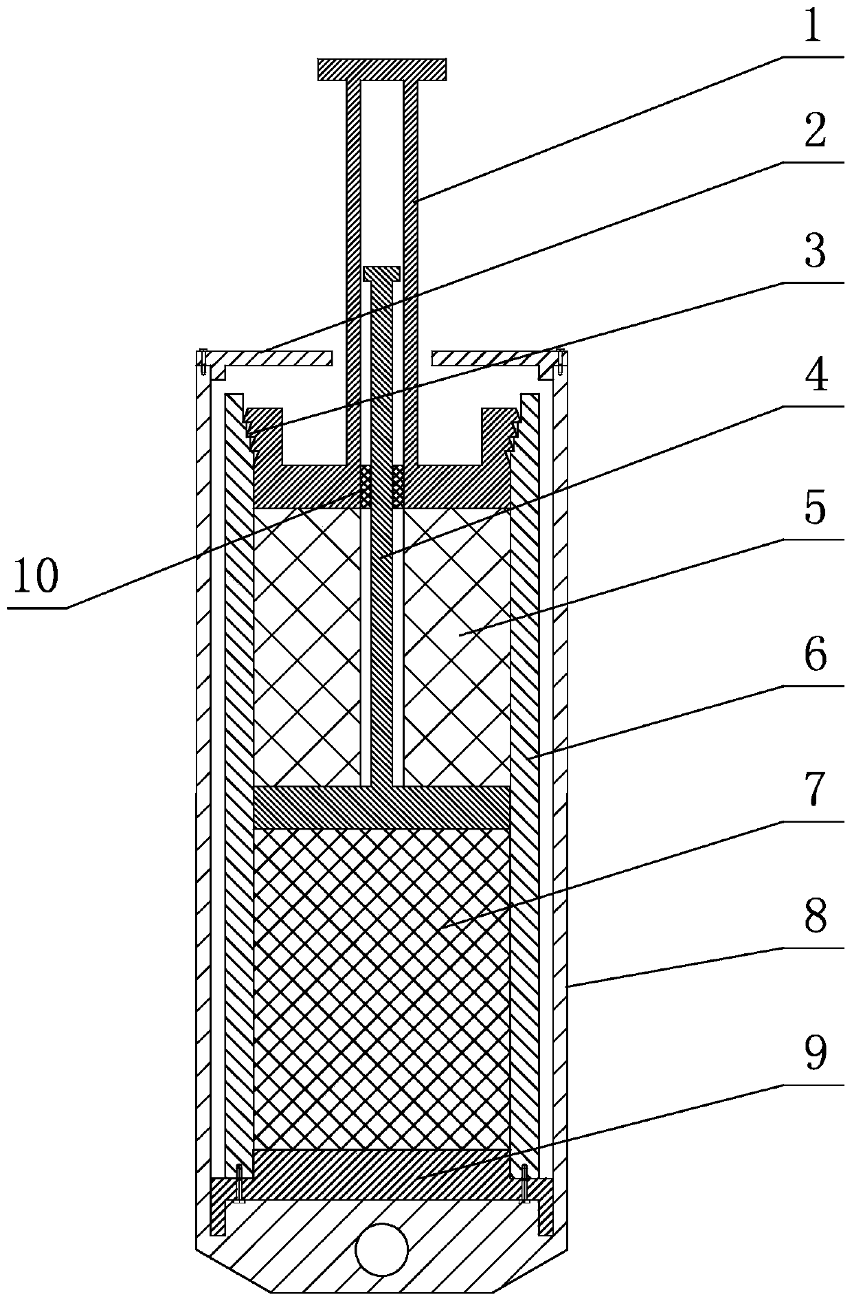
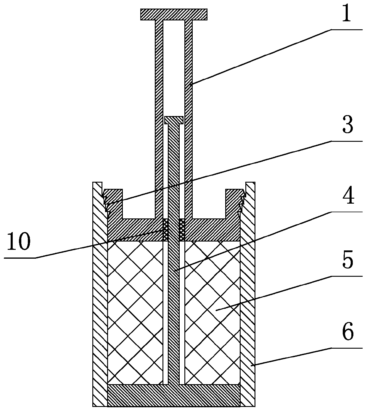
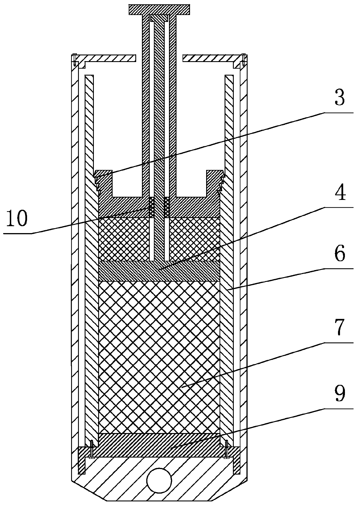
[0033] Specific implementation mode one: combine figure 1 , Figure 4 , Figure 6 and Figure 7 Describe this embodiment, a leg-type combined buffer for a recoverable rocket landing mechanism in this embodiment, it includes a buffer shell 8 and a buffer shell end cover 2, it also includes a first piston push rod 1, a broach 3. Second piston push rod 4, low-density metal honeycomb 5, buffer cavity 6, high-density metal honeycomb 7 and base 9,

[0034] The buffer housing 8 is a hollow cylinder structure, the buffer chamber 6 and the base 9 are sequentially arranged in the buffer housing 8 from top to bottom, the base 9 is fixed on the bottom of the buffer housing 8, and the buffer chamber 6 is fixed on the base 9 ,

[0035] The buffer cavity 6 is a hollow cylindrical structure, the first piston push rod 1, the low-density metal honeycomb 5, the second piston push rod 4 and the high-density metal honeycomb 7 are sequentially arranged in the buffer cavity 6 from top to bottom,...

specific Embodiment approach 2

[0042] Specific implementation mode two: combination Figure 6 Describe this embodiment, the broach 3 of this embodiment has three rows of cutter teeth, respectively the first row of cutter teeth 3-1, the second row of cutter teeth 3-2 and the third row of cutter teeth 3-3, the first row of cutter teeth The outer diameters of the cutter teeth 3-1, the second row of cutter teeth 3-2 and the third row of cutter teeth 3-3 decrease successively from the cutting-in end to the cutting-out end. With such arrangement, when the broach 3 moves axially downward, each tooth will cut off a certain thickness of metal from the inner wall of the buffer cavity 6, thereby realizing cutting energy absorption. Other compositions and connections are the same as in the first embodiment.

specific Embodiment approach 3

[0043] Specific implementation mode three: combination figure 1 The present embodiment will be described. The outer diameter of the broach 3 in this embodiment is smaller than the outer diameter of the buffer chamber 6 , and the inner diameter of the broach 3 is smaller than the inner diameter of the buffer chamber 6 . Other compositions and connections are the same as those in Embodiment 1 or Embodiment 2.


PUM


Abstract

The invention discloses a leg-type combined buffer for a recoverable rocket landing mechanism, and relates to the field of aerospace. The leg-type combined buffer for the recoverable rocket landing mechanism solves the problem that an existing landing buffer mechanism only adopts a metal honeycomb structure as buffer material resulting in relatively low impact energy absorbed per unit volume and non-satisfaction of the requirements of rocket landing recovery. In the leg-type combined buffer for the recoverable rocket landing mechanism, a buffer outer case is of a hollow cylindrical structure;a buffer cavity and a base are sequentially arranged in the buffer outer case from top to bottom; the base is fixed at the bottom of the buffer outer case; the buffer cavity is fixed on the base; thebuffer cavity is of a hollow cylindrical structure; a first piston push rod, a low-density metal honeycomb, a second piston push rod and a high-density metal honeycomb are sequentially arranged in thebuffer cavity from top to bottom; and the stiffness of the low-density metal honeycomb is less than the stiffness of the high-density metal honeycomb. The leg-type combined buffer for the recoverablerocket landing mechanism improves the buffer energy-absorption performance, thereby satisfying the requirements of rocket landing recovery.

Description

technical field [0001] The invention relates to the field of aerospace, in particular to a leg-type combined buffer for a recoverable rocket landing mechanism. Background technique [0002] Traditional launch vehicles cannot be reused after launch, resulting in high cost of space launch. The retrievable rocket realizes the soft landing of the rocket through the landing buffer mechanism, and realizes re-launch through simple maintenance and fuel supply on the ground, which can greatly reduce the launch cost. [0003] The metal honeycomb structure is widely used as a buffer material, but the impact energy absorbed per unit volume is low when a single metal honeycomb structure is used as a buffer material. The buffer forms are combined to improve the buffer energy absorption performance of the buffer, thereby meeting the requirements of rocket landing and recovery. [0004] To sum up, the existing landing buffer mechanism only uses metal honeycomb structure as the buffer mate...

Claims


Application Information

Patent Timeline
Patent Type & Authority Applications(China)
IPC IPC(8): B64G1/62
Inventor 高海波于海涛闫振丁亮刘振邓宗全
Owner HARBIN INST OF TECH
Why Eureka
Try Eureka