
Cryotube tray applied in automation equipment

A technology of automation equipment and cryopreservation tubes, which is applied to the preservation of human or animal bodies, biochemical equipment and methods, and applications. even force effect

Inactive Publication Date: 2019-05-07
INNOVEL INTELLIGENT TECH CO LTD
View PDF4 Cites 1 Cited by
  • Summary
  • Abstract
  • Description
  • Claims
  • Application Information

AI Technical Summary

Problems solved by technology

[0002] Cryopreservation tubes are containers used for storage of strains and cells in biological laboratories. Conventional cryopreservation tube trays are suitable for manual operation of cryopreservation tubes, which cannot match the production of mechanical automation. With the improvement of the degree of experiment automation, The problem of intelligent identification and automatic operation of the automation system is becoming more and more prominent. During the automatic operation, it is necessary to maintain the stability of the clamping and avoid the shaking of the cryotube tray caused by the unstable clamping, which will cause the overall instability. Therefore, an application is needed. Cryotube trays for automated equipment improve the above problems

Method used


Image

  • Cryotube tray applied in automation equipment
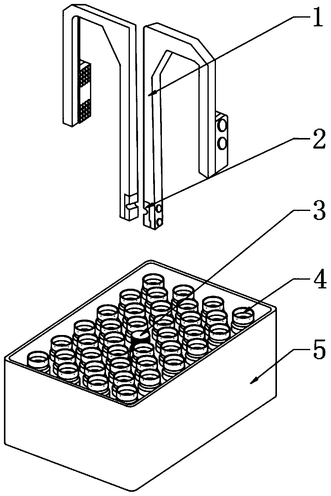
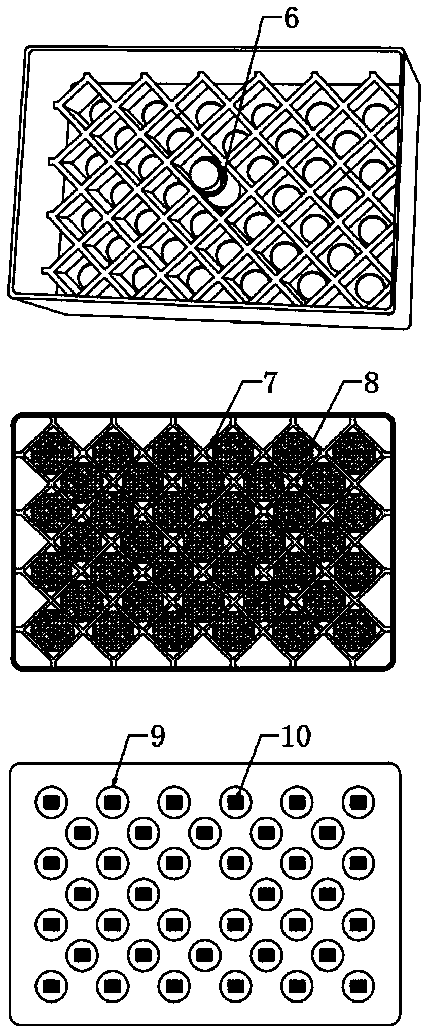
  • Cryotube tray applied in automation equipment
  • Cryotube tray applied in automation equipment

Examples


Embodiment Construction

[0020] The technical solutions in the embodiments of the present invention will be clearly and completely described below in conjunction with the accompanying drawings in the embodiments of the present invention. Obviously, the described embodiments are only some of the embodiments of the present invention, not all of them. Based on The embodiments of the present invention and all other embodiments obtained by persons of ordinary skill in the art without making creative efforts belong to the protection scope of the present invention.

[0021] see Figure 1-3 , the present invention provides a technical solution:

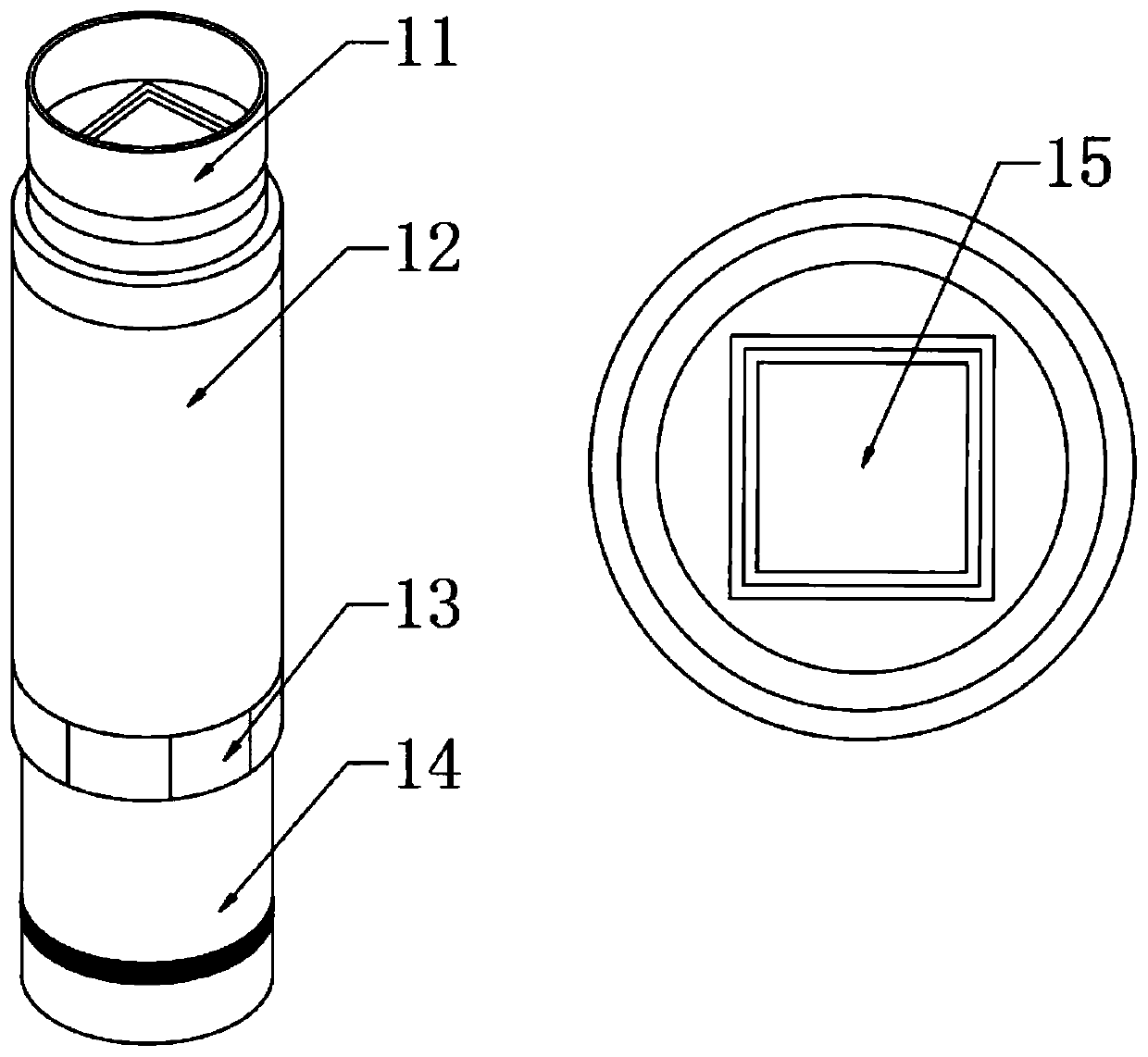
[0022] A cryopreservation tube tray applied to automation equipment, comprising a mechanical gripper 1, a cryopreservation tube main body 4 and a tray main body 5, one end of the mechanical gripper 1 is provided with a jaw 2, and the side of the jaw 2 away from the mechanical gripper 1 A tray main body 5 is provided, and there are multiple sets of regular octagonal ...


PUM


Abstract

The present invention relates to the technical field of trays and particularly discloses a cryotube tray applied in automatic equipment. The cryotube tray comprises a mechanical clamp hand, cryotube main bodies and a tray main body, one end of the mechanical clamp hand is provided with a clamping mouth, one side, far away from the mechanical clamp hand, of the clamping mouth is provided with the tray main body, a plurality of sets of regular octagonal clamping and holding mouths are arranged inside the tray main body, lower ends of the regular octagonal clamping and holding mouths are providedwith tray circular through-holes, a partitioning plate is arranged at upper ends of the regular octagonal clamping and holding mouths, the tray circular through-holes are internally provided with thecryotube main bodies, the cryotube main body comprises a two-dimensional code, a cryotube top cover, a cryotube body, a cryotube octagonal main body, a cryotube circular tube bottom and a square rotating hole, and a fixed clamping and holding column is arranged in a middle place of the tray main body. The arranged two-dimensional code facilitates intelligent identification of an automation system, and the cryotube tray performs automatic operation, is adapted to the mechanical clamp hand to conduct an automatic taking operation by optimizing structure, and is simple in structure and assemblyand easy to implement.

Description

technical field [0001] The invention relates to the technical field of trays, in particular to a cryopreservation tube tray applied to automation equipment. Background technique [0002] Cryopreservation tubes are containers used for storage of strains and cells in biological laboratories. Conventional cryopreservation tube trays are suitable for manual operation of cryopreservation tubes, which cannot match the production of mechanical automation. With the improvement of the degree of experiment automation, The problem of intelligent identification and automatic operation of the automation system is becoming more and more prominent. During the automatic operation, it is necessary to maintain the stability of the clamping and avoid the shaking of the cryotube tray caused by the unstable clamping, which will cause the overall instability. Therefore, an application is needed. The cryopreservation tube tray for automated equipment improves the above problems. Contents of the ...

Claims


Application Information

Patent Timeline
Patent Type & Authority Applications(China)
IPC IPC(8): C12M1/24C12M1/00A01N1/02
Inventor 余春
Owner INNOVEL INTELLIGENT TECH CO LTD
Learn More