Two-stage speed reduction mechanism for speed reducer of pure electric vehicle

A two-stage deceleration technology for pure electric vehicles, which is applied to mechanical equipment, transmission devices, transmission device parts, etc., can solve the problems of high performance requirements for drive motors, reduced mileage of pure electric vehicles, and high energy consumption of drive motors. Achieve the effect of improving power performance, simple and effective transmission, and simple and compact structure

Active Publication Date: 2019-05-07
CHONGQING TSINGSHAN IND
View PDF11 Cites 4 Cited by
  • Summary
  • Abstract
  • Description
  • Claims
  • Application Information

AI Technical Summary

Problems solved by technology

However, the power performance of a pure electric vehicle using a single-stage reduction mechanism depends entirely on the drive motor, and the performance requirements for the drive motor are relatively high.
In actual road conditions, the motor of a pure electric vehicle with a single-stage transmission mechanism cannot always work in the optimal efficiency zone, especially when driving at the highest or lowest speed and low load state, the energy consumption of the driving motor is large and the efficiency is low. Low, reducing the cruising range of pure electric vehicles, the economy of the car is not high

Method used


Image

  • Two-stage speed reduction mechanism for speed reducer of pure electric vehicle

Examples


Embodiment Construction

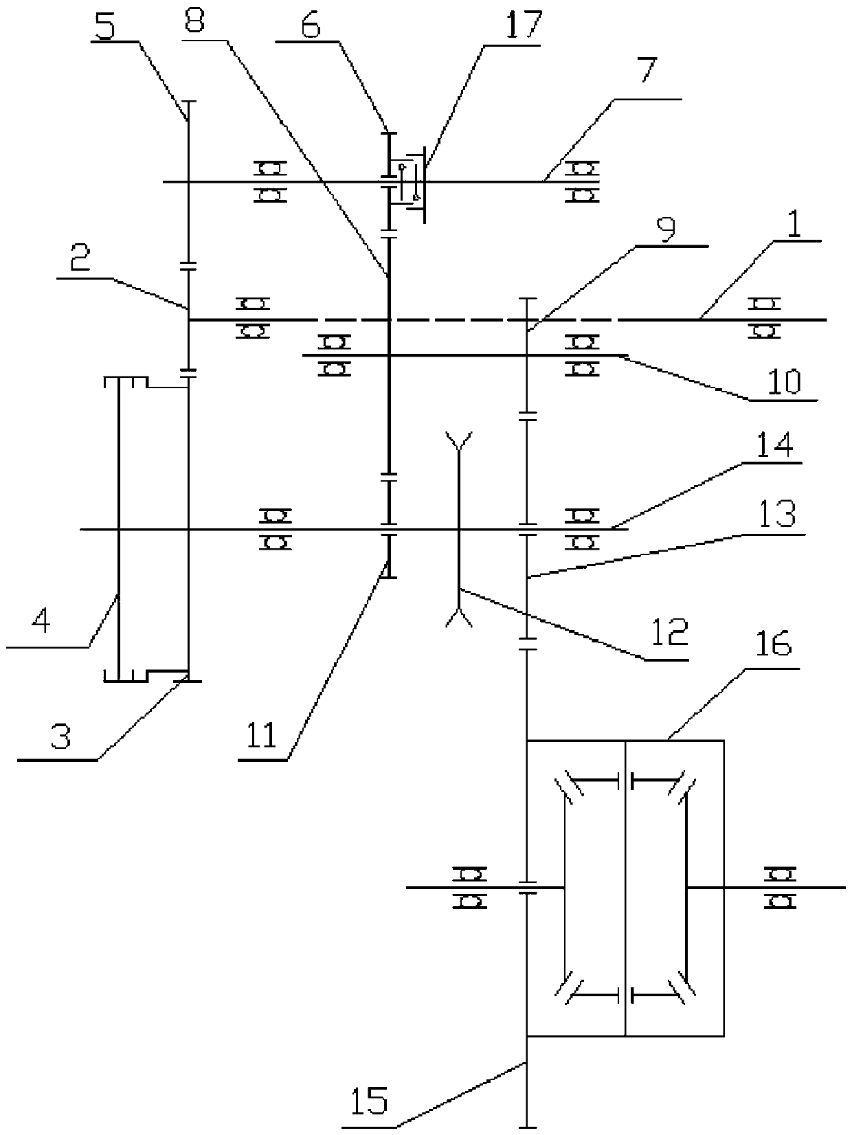
[0017] see figure 1 , a two-stage reduction mechanism of a pure electric vehicle reducer, including an input shaft 1, a differential 16, and a first layshaft 7, a second layshaft 14, an intermediate shaft 10, the first layshaft 7, The second layshaft 14 and the intermediate shaft 10 are parallel to the input shaft 1 . An input driving gear 2 is fixedly arranged on the input shaft 1, and the input shaft 1 is connected with the driving motor of the pure electric vehicle and is driven to rotate by the driving motor. The first driven gear 5 and the one-way overrunning clutch 17 are fixed circumferentially on the first countershaft 7 , and the first driven gear 5 and the first countershaft 7 are circumferentially fixed by splines. A second countershaft clutch 4 and a synchronizer 12 are fixed circumferentially on the second countershaft 14 , and the first driven gear 5 and the gear 3 of the second countershaft clutch 4 are co-engaged with the input drive gear 2 . The driving disc...


PUM


Abstract

The invention relates to a two-stage speed reduction mechanism for a speed reducer of a pure electric vehicle. The two-stage speed reduction mechanism for the speed reducer of the pure electric vehicle comprises a differential mechanism as well as an input shaft, a first auxiliary shaft, a second auxiliary shaft and a middle shaft which are mutually parallel, wherein an input drive gear is fixed to the input shaft; a first driven gear and a one-way overrunning clutch are fixedly arranged in the circumferential direction of the first auxiliary shaft; a second auxiliary shaft clutch and a synchronizer are fixedly arranged in the circumferential direction of the second auxiliary shaft; the first driven gear and a gear of the second auxiliary shaft clutch are co-engaged with the input drive gear; a first drive gear is arranged on the first auxiliary shaft in a manner of slide fit; the first drive gear is connected with the first auxiliary shaft through the one-way overrunning clutch; a reverse gear and an output gear are arranged on the second auxiliary shaft in a manner of slide fit separately; the reverse gear and a second gear are located at the two sides of the synchronizer separately; the second gear is engaged with a differential mechanism input gear of the differential mechanism; a first driven gear and a transmission gear are fixedly arranged on the middle shaft; the firstdriven gear is co-engaged with the first drive gear and the reverse gear; and the transmission gear is engaged with the second gear.

Description

technical field [0001] The invention relates to the field of pure electric vehicles, in particular to a two-stage deceleration mechanism of a pure electric vehicle reducer. Background technique [0002] At present, traditional pure electric vehicles all use a single-stage reduction mechanism with a fixed speed ratio, and its performance can basically meet the driving requirements of the vehicle. However, the power performance of a pure electric vehicle using a single-stage reduction mechanism depends entirely on the drive motor, and the performance requirements for the drive motor are relatively high. In actual road conditions, the motor of a pure electric vehicle with a single-stage transmission mechanism cannot always work in the optimal efficiency zone, especially when driving at the highest or lowest speed and low load state, the energy consumption of the driving motor is large and the efficiency is low. Low, reducing the cruising range of pure electric vehicles, the ec...

Claims


Application Information

Patent Timeline
Patent Type & Authority Applications(China)
IPC IPC(8): F16H3/10F16H61/32F16H57/023
Inventor 彭飞杨鸿徐迪马雄刘冲池强张代明张子川周思成
Owner CHONGQING TSINGSHAN IND
Why Eureka
Try Eureka