Relay state detecting circuit and method thereof

A state detection, relay technology, applied in the direction of circuit breaker testing, etc., can solve the problems of unable to determine the faulty relay, unable to determine the specific faulty relay, etc., to achieve the effect of easy repair

Inactive Publication Date: 2019-05-07
HAIMA AUTOMOBILE CO LTD +1
View PDF8 Cites 4 Cited by
  • Summary
  • Abstract
  • Description
  • Claims
  • Application Information

AI Technical Summary

Problems solved by technology

[0004] In view of this, the purpose of the present invention is to provide a relay state detection circuit to solve the problem that the specific relay that fails cannot be determined in the prior art
[0005] Another object of the present invention is to provide a relay state detection method to solve the problem in the prior art that the specific relay that fails cannot be determined

Method used


Image

  • Relay state detecting circuit and method thereof
  • Relay state detecting circuit and method thereof
  • Relay state detecting circuit and method thereof

Examples


no. 1 example

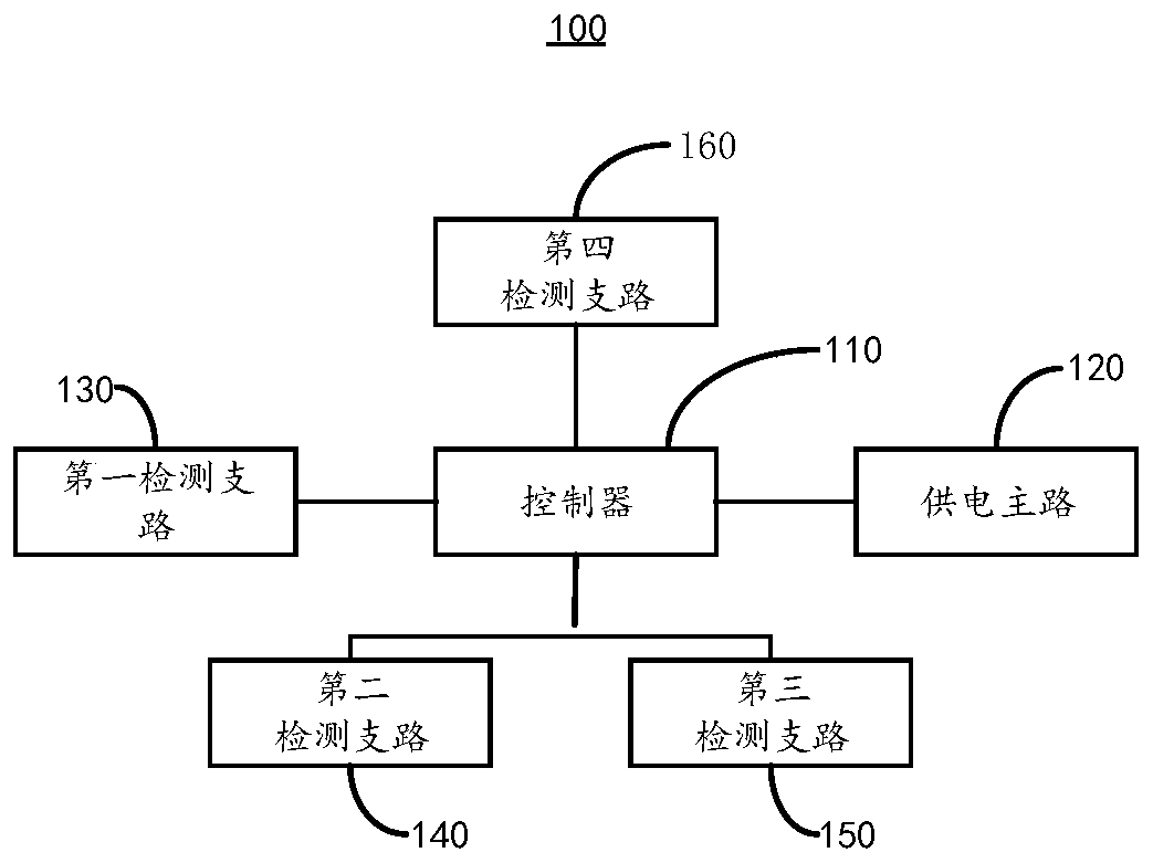
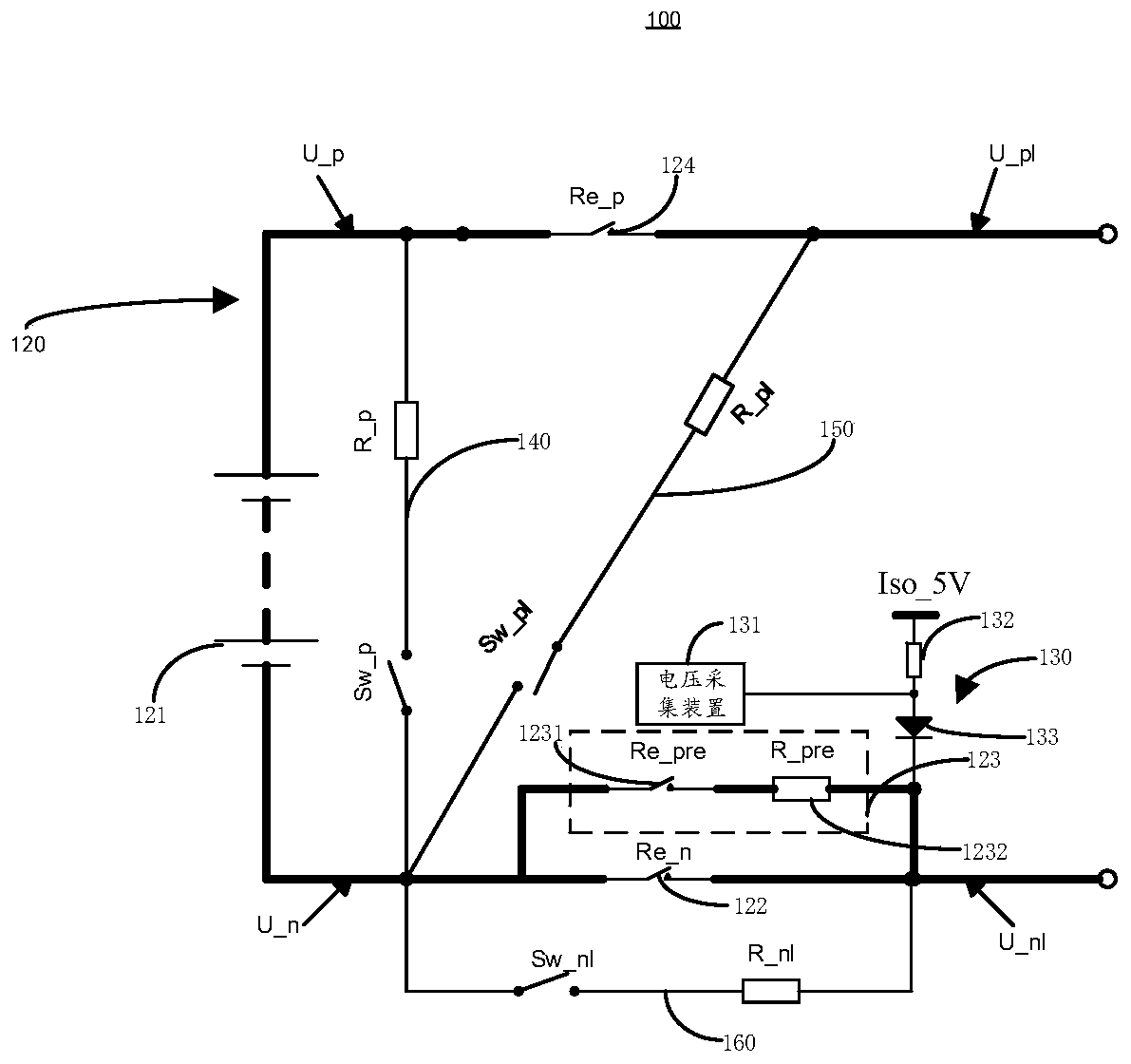
[0038] see figure 1 and figure 2 , the embodiment of the present invention provides a relay state detection circuit 100, the relay state detection circuit 100 includes a controller 110, a main power supply circuit 120, a first detection branch 130, a second detection branch 140, a third detection branch 150 and the fourth detection branch 160, the controller 110 is electrically connected to the power supply main circuit 120, the first detection branch 130, the second detection branch 140, the third detection branch 150 and the fourth detection branch 160, and The main power supply circuit 120 includes a first power source 121 , a main positive relay 124 , a main negative relay 122 and a pre-charging relay group 123 . Wherein, the main positive relay 124 is electrically connected to the positive pole of the first power supply 121 , and the main negative relay 122 is electrically connected to the negative pole of the first power supply 121 after being connected in parallel wit...

no. 2 example

[0057] see image 3 The embodiment of the present invention provides a relay state detection method, which is applied to the relay state detection circuit 100 of the first embodiment. The circuit structure of the relay state detection circuit 100 is not described in this embodiment. Specifically, the relay state detection method includes:

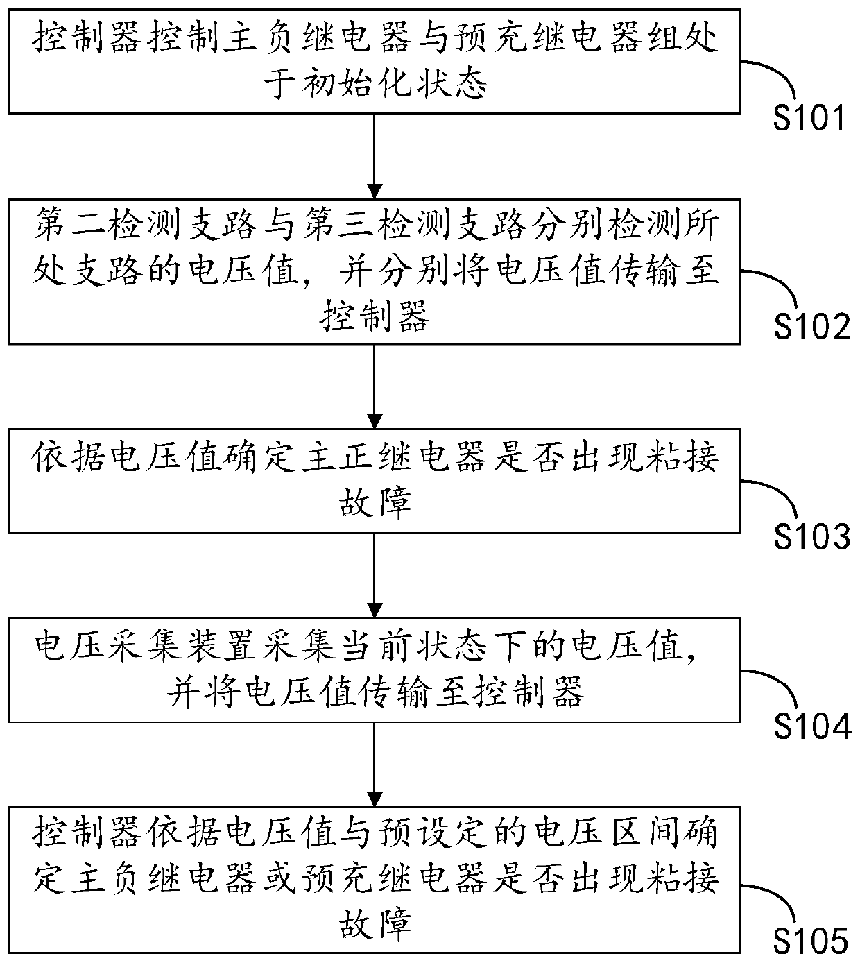
[0058] S101, the controller controls the main negative relay and the pre-charge relay group to be in an initialization state.

[0059] S102. The second detection branch and the third detection branch respectively detect the voltage values ​​of the respective branches, and transmit the voltage values ​​to the controller respectively.

[0060] S103. Determine whether the main positive relay has a bonding fault according to the voltage value.

[0061] Wherein, when both the second detection branch 140 and the third detection branch 150 detect a voltage value, it means that the main positive relay 124 fails; when the second detection branch 1...


PUM


Abstract

The invention provides a relay state detecting circuit and a method thereof, and relates to the technical field of electric vehicles. The relay state detecting circuit comprises a controller, a powersupply main circuit and a first detecting branch, wherein the power supply main circuit comprises a first power source, a main negative relay and a pre-charge relay group; one end of the main negativerelay connected in parallel to the pre-charge relay group is electrically connected to the negative pole of the first power source, the pre-charge relay group comprises a pre-charge relay, the otherend of the main negative relay connected in parallel to the pre-charge relay group is electrically connected to the first detecting branch, the input end of the first detecting branch is electricallyconnected to a second power source, the first detecting branch comprises a voltage collecting device, and the controller is electrically connected to the main negative relay, the pre-charge relay, andthe voltage collecting device, respectively. The relay state detecting circuit and the method thereof provided by the invention have the advantages of determining a specific relay in which a bondingfailure occurs when a relay has a bonding failure, and facilitating subsequent repairing.

Description

technical field [0001] The invention relates to the technical field of electric vehicles, in particular to a relay state detection circuit and a method thereof. Background technique [0002] In electric vehicles, the relay is used to control the opening and closing of the high-voltage circuit. In order to ensure the safety of the high-voltage circuit, it is necessary to detect the state of the relay before or after the relay is activated to detect whether the relay has a bonding failure. [0003] However, although the current detection of the relay state can detect whether there is a relay in the circuit that has a bonding failure, it is impossible to determine which relay is faulty, which makes it difficult to repair the subsequent relay. Contents of the invention [0004] In view of this, the object of the present invention is to provide a relay state detection circuit to solve the problem in the prior art that the specific relay that fails cannot be determined. [0005...

Claims


Application Information

Patent Timeline
IPC IPC(8): G01R31/327
Inventor 王明林蒋峰刘珂贾晓光
Owner HAIMA AUTOMOBILE CO LTD
Why Eureka
Try Eureka