
Novel sequential switching waveguide switch

A waveguide switch and sequential technology, applied to waveguide devices, electrical components, circuits, etc., can solve the problems of lower product reliability, many control modules, and complex structures, so as to reduce the number of parts, improve reliability, and reduce complexity. degree of effect

Active Publication Date: 2019-05-07
CHINA AEROSPACE TIMES ELECTRONICS CORP
View PDF2 Cites 11 Cited by
  • Summary
  • Abstract
  • Description
  • Claims
  • Application Information

AI Technical Summary

Problems solved by technology

Its complex structure and many control modules lead to difficult assembly and debugging, high failure rate, reduced product reliability, and difficulty in meeting the requirements of miniaturization, light weight and complex space environment

Method used


Image

  • Novel sequential switching waveguide switch
  • Novel sequential switching waveguide switch
  • Novel sequential switching waveguide switch

Examples


Embodiment Construction

[0032] The present invention is described in conjunction with accompanying drawing.

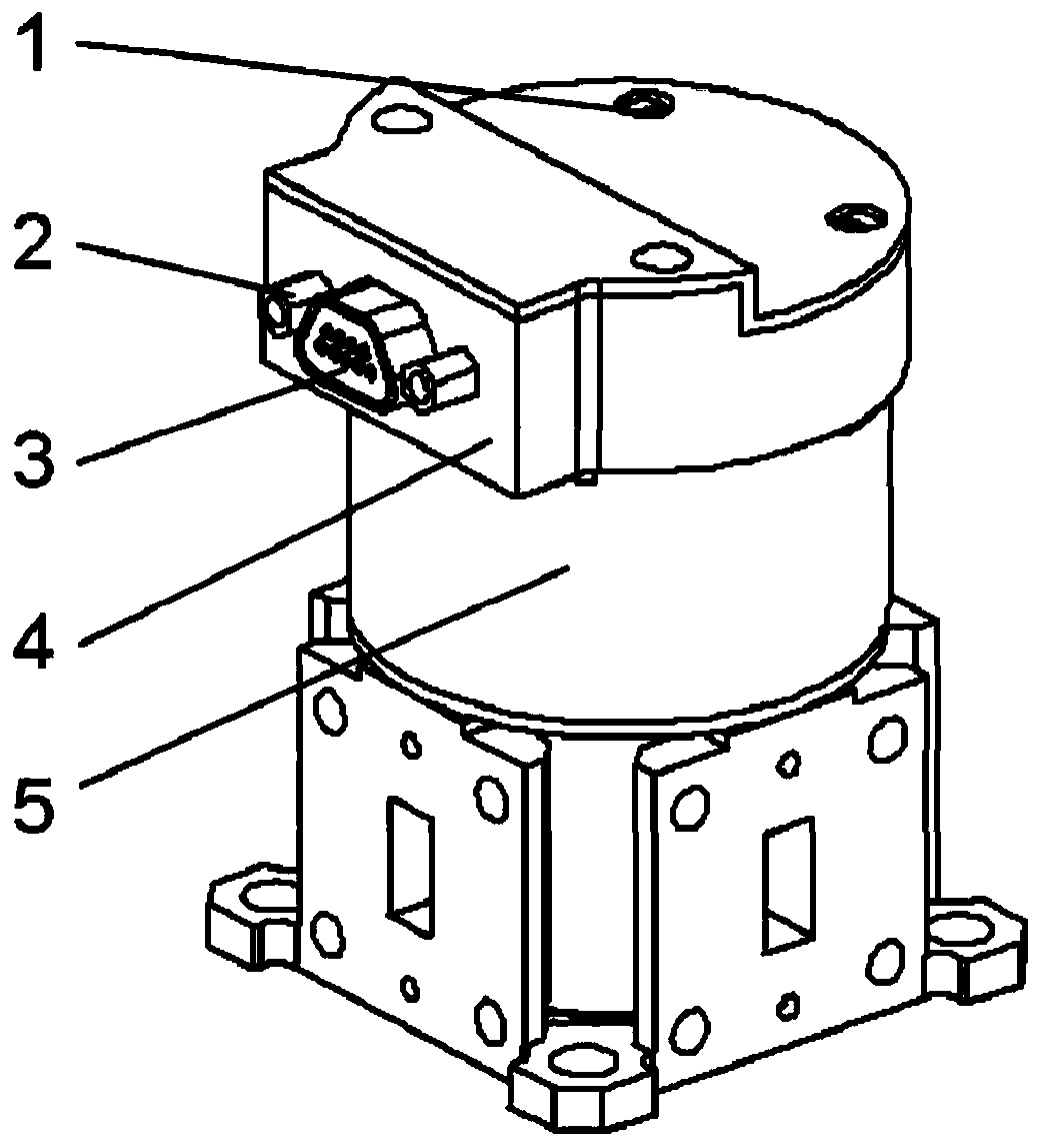
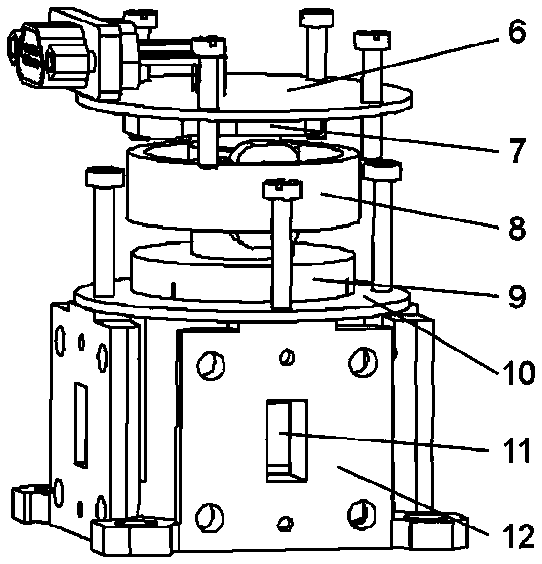
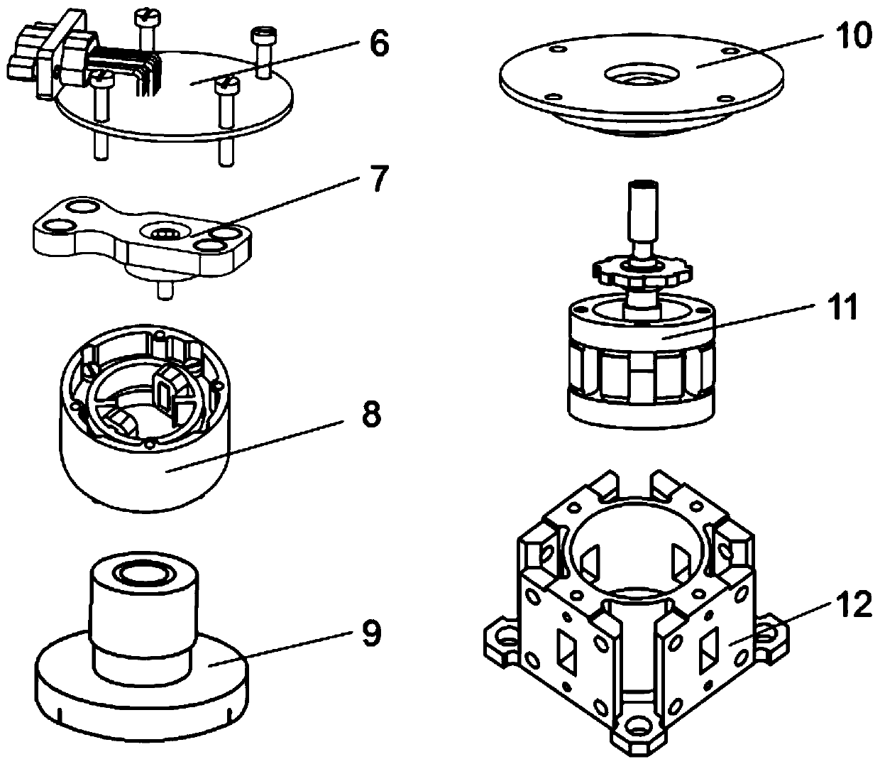
[0033] like figure 1 , figure 2 , image 3 As shown, the present invention sequentially switches the waveguide switch, including the upper casing 4, the circuit board group 6, the position feedback assembly 7, the drive stator group 8, the rotor group 9, the bearing seat assembly 10, the guide rotor group 11 and the guide stator group 12. The upper housing 4 is fixed above the middle housing 5 by mounting screws 1; the circuit board group 6 is located above the position feedback assembly 7, and the D-Sub connector 3 is fastened to the upper housing 4 by fastening screws 2; the drive stator group 8 It is fixed above the rotor group 9; the bearing block assembly 10 is fixed together with the guiding stator group 11; the guiding rotor group 11 is assembled in the guiding stator group 12.

[0034] like Figure 4 As shown, the circuit board group 6 is installed in the upper casing 2 through ...


PUM


Abstract

A novel sequential switching waveguide switch includes an upper casing and the like; the upper casing is fixed at the upper portion of a driving stator group, the position feedback component is installed at the bottom portion of a circuit board group, and the circuit board group is installed in an upper casing group; a D-Sub connector is installed at one side of the upper casing group; the lower portion of a guiding rotor group is assembled in a guiding stator group, and the lower portion thereof is matched with a bearing base module through a shaft; the driving stator group is installed at the upper portion of a rotor group, and the rotor group is installed at the upper portion of the bearing base module and is matched with the shaft of the guiding rotor group. The novel sequential switching waveguide switch employs a monostable motor to match with a ratchet transmission mechanism, employs the locking magnetic steel to perform position locking, and converts the 45-degree reciprocatingmotion of the monostable motor to the 45-degree directional rotation of the guiding rotor so as to achieve sequential switching of the four states of the switch. The novel sequential switching waveguide switch reduces the complex degree of the control device, reduces the number of drive interfaces, is compact in product structure, improves the product reliability, and facilitates achievement of the miniaturization and weight reduction of the switch.

Description

technical field [0001] The invention relates to a waveguide switch. Background technique [0002] The waveguide switch is mainly used for the transmission of microwave signals and the switching of transmission channels in satellite communication systems. Its main function is to realize the selection of link transmission channels through the switching of radio frequency channels, thereby greatly improving the reliability of the link system. [0003] With the development of aerospace technology, space resources are becoming increasingly tight, and the development of systems towards integration and miniaturization has become a development trend. As a key component of the communication system, the waveguide switch has an important impact on the development of the whole system due to its miniaturization and light weight. [0004] The existing sequential switching waveguide switch is mainly realized through a complex magnetic circuit transmission mechanism. Its complex structure...

Claims


Application Information

Patent Timeline
Patent Type & Authority Applications(China)
IPC IPC(8): H01P1/11
Inventor 李刚蔡立兵卢泰安苌群峰张楚贤田亚伟钟翔宁张军傲
Owner CHINA AEROSPACE TIMES ELECTRONICS CORP
Learn More