
A photovoltaic module and a manufacturing method thereof

A photovoltaic module and manufacturing method technology, applied in photovoltaic power generation, photovoltaic modules, electrical components, etc., can solve problems such as lowering the energy conversion efficiency of photovoltaic modules, low energy conversion efficiency of photovoltaic modules, and rising operating temperature of photovoltaic modules, and achieves a simple structure , easy installation, avoid the effect of temperature rise

Inactive Publication Date: 2019-05-07
SUNGROW POWER SUPPLY CO LTD
View PDF1 Cites 0 Cited by
  • Summary
  • Abstract
  • Description
  • Claims
  • Application Information

AI Technical Summary

Problems solved by technology

[0003] In some photovoltaic systems, the ventilation conditions around the photovoltaic modules are poor, and the angle between the photovoltaic modules and the ground is small, so a large amount of hot air gathers on the back of the photovoltaic modules, resulting in a sharp rise in the operating temperature of the photovoltaic modules
The increase in temperature will significantly reduce the energy conversion efficiency of photovoltaic modules, which will convert more solar energy into heat energy, thus creating a vicious circle, making the energy conversion efficiency of photovoltaic modules lower and lower

Method used


Image

  • A photovoltaic module and a manufacturing method thereof
  • A photovoltaic module and a manufacturing method thereof
  • A photovoltaic module and a manufacturing method thereof

Examples


Embodiment 1

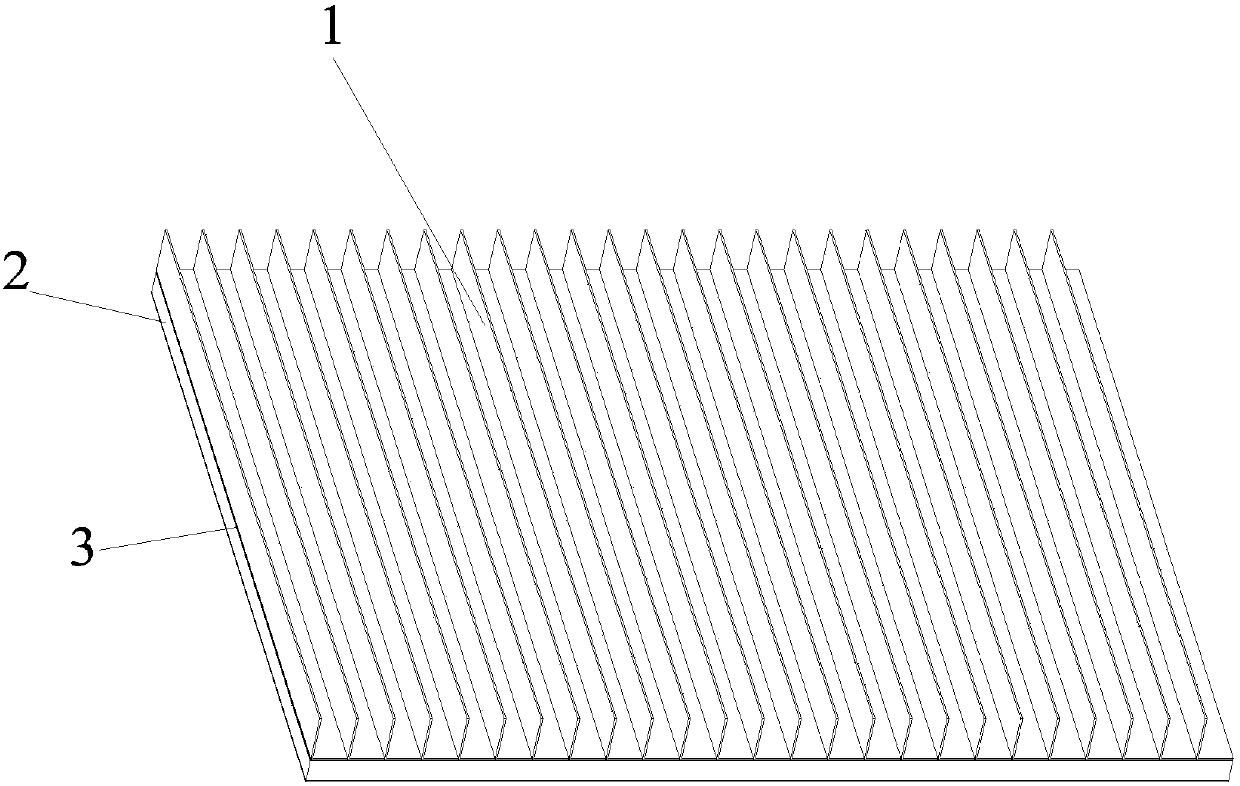
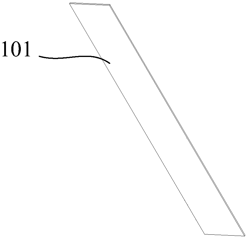
[0047] Please refer to Figure 1 to Figure 5 , in this embodiment, the photovoltaic module is specifically rectangular, and the heat dissipation fins 1 are processed with a metal slab 101 with a thinner thickness and excellent thermal conductivity. The material of the metal slab 101 is aluminum and its alloys, copper and its alloys. The shape of the fins 1 is elongated, and multiple heat dissipation fins 1 are arranged side by side on the back of the photovoltaic module body 2 , and the heat dissipation fins 1 are parallel to a pair of sides of the photovoltaic module.

[0048] In order to improve the heat dissipation effect as much as possible, the bonding part 12 of the heat dissipation fin 1 in this embodiment completely covers the back of the photovoltaic module body 2, which can ensure that the heat dissipation fin 1 can dissipate the heat from the back of the photovoltaic module body 2 as much as possible. spread out as figure 1 with Figure 4 shown in .

[0049] The ...

Embodiment 2

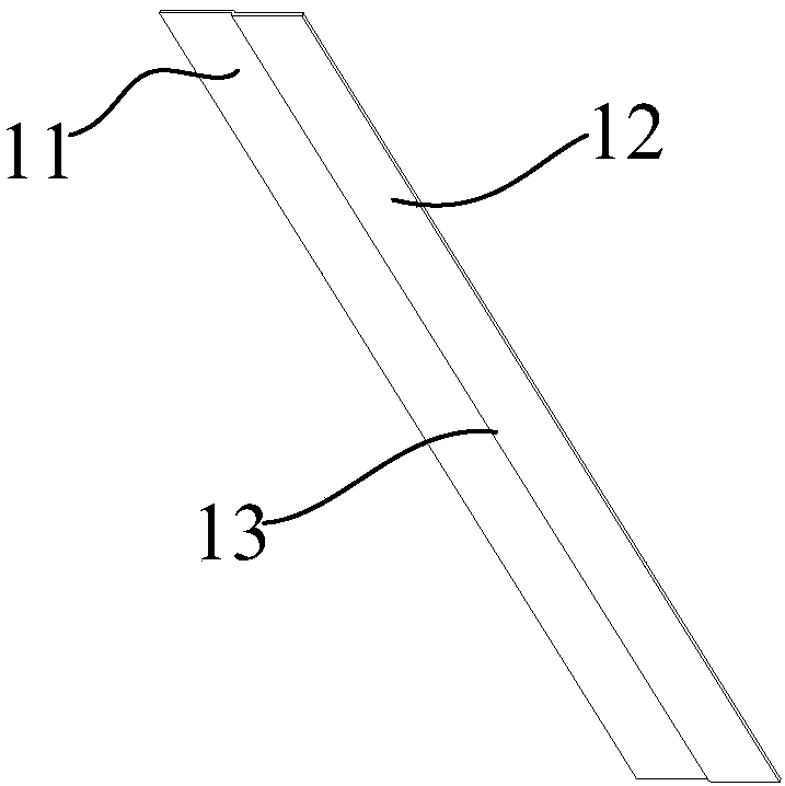
[0064] Please refer to Figure 6 to Figure 11 , in this embodiment, the photovoltaic module is specifically rectangular, and the heat dissipation fin 1 is processed with a metal slab 101 with a thinner thickness and excellent thermal conductivity. The material of the metal slab 101 is aluminum and its alloys, copper and its alloys, such as Figure 7 As shown in , the processed metal slab 101 forms a fin array, and the fin array includes a plurality of heat dissipation fins 1, any heat dissipation fin 1 includes a bonding part 12 and a bent heat dissipation part 11, and the bonding The part 12 is attached to the back of the photovoltaic module body 2 , and the bent heat dissipation part 11 is bent toward the side away from the back of the photovoltaic module body 2 .

[0065] In order to improve the heat dissipation effect as much as possible, the bonding part 12 of the heat dissipation fin 1 in this embodiment completely covers the back of the photovoltaic module body 2, which...


PUM


Abstract

The invention relates to a photovoltaic module, which comprises a photovoltaic module body and a heat dissipation fin, and is characterized in that the heat dissipation fin is provided with an attaching part and a bent heat dissipation part, the attaching part is attached to the back surface of the photovoltaic module body, and the bent heat dissipation part is bent away from the back surface of the photovoltaic module body. The heat dissipation fin can effectively prevent the temperature of the photovoltaic module from rising, so that the photovoltaic module works in a proper temperature range, and the photovoltaic module is ensured to have ideal energy conversion efficiency. Besides, the structure is simple, the installation is convenient, the heat can be dissipated for a long time almost without any maintenance, and the manufacturing, installation and later maintenance costs of the photovoltaic module are effectively reduced. The invention further relates to a manufacturing method of the photovoltaic module.

Description

technical field [0001] The invention relates to the technical field of photovoltaic module production and manufacturing, in particular to a photovoltaic module and a manufacturing method thereof. Background technique [0002] Photovoltaic modules are a key component of photovoltaic systems, and the energy conversion efficiency of photovoltaic modules is an important factor that restricts the efficiency of the entire photovoltaic system. In order to ensure the absorption efficiency of photovoltaic modules to sunlight, the angle between photovoltaic modules and the ground is set to be small. However, during the energy conversion process of photovoltaic modules, a large part of solar energy is not converted into electrical energy, but in the form of thermal energy. released into the environment around the PV module. [0003] In some photovoltaic systems, the ventilation conditions around the photovoltaic modules are poor, and the angle between the photovoltaic modules and the ...

Claims


Application Information

Patent Timeline
Patent Type & Authority Applications(China)
IPC IPC(8): H02S40/42
CPCY02E10/50
Inventor 关鹏云平朱晓亮时晓蕾
Owner SUNGROW POWER SUPPLY CO LTD
Learn More