Network fault delimiting method and device and computer storage medium

A fault and network technology, applied in the field of communication, which can solve the problems of large switch configuration, inability to complete network fault demarcation, and many forwarding paths.

Active Publication Date: 2019-05-07
HUAWEI TECH CO LTD
View PDF5 Cites 4 Cited by
  • Summary
  • Abstract
  • Description
  • Claims
  • Application Information

AI Technical Summary

Problems solved by technology

When a network failure occurs, although the equipment used for fixed demarcation detects the failed Internet Protocol (Intent Protocol, IP) pair, due to the existence of many forwarding paths, the traditional Internet packet explorer (Packet Internet Groper, ping ) and route tracking (transroute) methods cannot complete the fault demarcation of the network, so in the prior art, often adopt Network Quality Analyzer (Network Quality Analyzer, NQA) technology to carry out the fault demarcation of the network, NQA technology sends test message, Analyze network performance or service quality, and determine the location of the fault based on the analysis results
[0004] However, the NQA technology needs to configure parameters for each link of each switch in the network. A switch usually includes multiple links, and the configuration of each link is different, resulting in a huge amount of switch configuration, and the Technology is greatly affected by network changes. For example, when the IP address of a certain port of a switch changes, the link where the IP address is located needs to be reconfigured, which will also increase the configuration amount of the switch.

Method used


Image

  • Network fault delimiting method and device and computer storage medium
  • Network fault delimiting method and device and computer storage medium
  • Network fault delimiting method and device and computer storage medium

Examples


Embodiment Construction

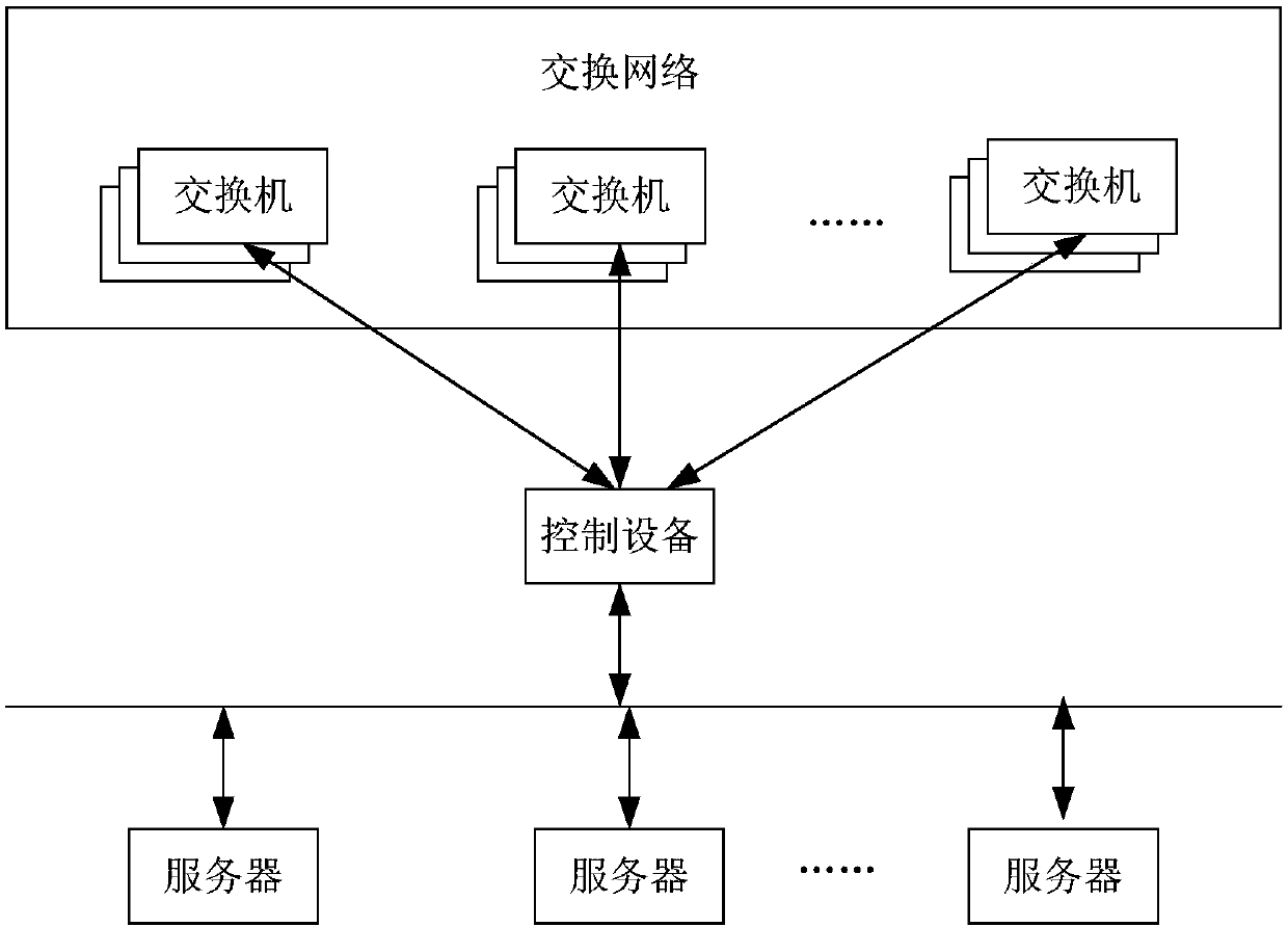
[0090] This application provides a method for demarcating network faults, figure 1 A schematic diagram of the network architecture applicable to this application, such as figure 1 As shown, the network architecture includes: a switching network, a control device and a server. The switching network is composed of multiple switches, and the switching network may be a CLOS network. There are multiple servers, and the service interaction between the servers needs to go through the switching network. The control device is a newly added device in this application, and the control device can communicate with the server and the switch, where the control device and the switch can communicate through Simple network management protocol (SNMP).

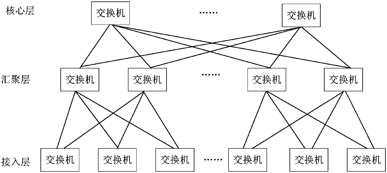
[0091] figure 2 It is a schematic diagram of the structure of the CLOS network, such as figure 2 As shown, the CLOS network consists of three layers of switches: access layer, aggregation layer, and core layer. Among them, switches located ...


PUM


Abstract

The invention provides a network fault delimiting method and device, and a computer storage medium. The method comprises the following steps: the control device sends a fault detection indication message to a server used for fault delimiting, wherein the fault indication message is used for indicating the server to send a tracking message by using a to-be-tracked fault IP pair, wherein the controldevice receives the number of the tracking messages sent by each switch in the network, the number of the tracking messages is obtained by the switches according to a message matching strategy, the message matching strategies on the switches are the same, and the control device determines the switches with faults according to the number of the tracking messages sent by the switches. According tothe method, the message matching strategies on the switches are the same, and the message matching strategies of the switches are not influenced by networking, so that the configuration quantity of the switches is greatly reduced, fault delimiting is performed according to the number of tracking messages, and the method is simple to implement and quick and accurate in delimiting.

Description

technical field [0001] The present application relates to communication technologies, and in particular to a network fault demarcation method, device and computer storage medium. Background technique [0002] The service interaction between servers needs to go through multiple switching devices. Any hardware and / or software failure of any switching device in the network will cause the loss of service packets. Therefore, when the network fails, it is necessary to quickly diagnose the network fault. boundary, that is, to quickly find the faulty switching device. With the increase of network scale and complexity, the difficulty of network fault demarcation also increases gradually. [0003] Taking the CLOS (Claus) network as an example, the CLOS network adopts a multi-level switching architecture, and there are multiple equal-cost routes (Equal Cost Multi-Path, ECMP) in the CLOS network, so that it can achieve non-blocking. When a switching device forwards a packet, it can se...

Claims


Application Information

Patent Timeline
Patent Type & Authority Applications(China)
IPC IPC(8): H04L12/24H04L12/26
Inventor 徐俊杰袁舟王建
Owner HUAWEI TECH CO LTD
Why Eureka
Try Eureka