Wing spar aligning tooling and aligning method

A technology of wing spar and tooling, which is applied in the field of aligning tooling for automatic hole-making of wing spar, can solve the problems that the hole-making accuracy cannot meet the production requirements, and cannot accurately measure the length error of the wing spar, so as to realize the automatic hole-making operation and improve the The effect of hole making accuracy

Active Publication Date: 2020-10-02
上海麦可洛自动化科技有限公司
View PDF6 Cites 0 Cited by
  • Summary
  • Abstract
  • Description
  • Claims
  • Application Information

AI Technical Summary

Problems solved by technology

[0003] In order to overcome the inability of the existing automatic hole-making equipment to accurately measure the spar length error caused by shot peening, resulting in the hole-making accuracy not meeting the production requirements, etc., the technical problem to be solved by the present invention is: to provide a hole-making equipment that can Provides a reference for alignment, alignment tooling and alignment methods for correcting hole position deviations caused by wing spar machining errors

Method used


Image

  • Wing spar aligning tooling and aligning method

Examples


Embodiment Construction

[0021] The present invention will be further described below in conjunction with the accompanying drawings.

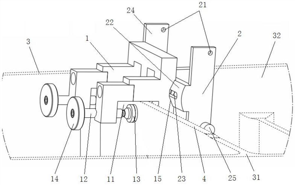
[0022] Such as figure 1 As shown, the spar alignment tooling of the present invention includes a vertical rib positioning block 1 and a sliding positioning block 2, and the vertical rib positioning block 1 is provided with a locking bayonet that can be stuck on the vertical rib 4 of the spar 3 , the sliding positioning block 2 is slidingly connected with the vertical rib positioning block 1, and the sliding direction is consistent with the width direction of the vertical rib 4. One end of the sliding positioning block 2 is provided with an offset reference hole 21, and the offset reference hole 21 exceeds The spar end face 31 and its axis are perpendicular to the spar cap inner surface 32 .

[0023] The invention utilizes the internal structure of the spar-rib position and vertical ribs to provide a reference for the hole-making equipment. The vertical rib 4 of the s...


PUM


Abstract

The invention discloses an alignment tool and alignment method for spar automatic hole formation in the technical field of aircraft manufacturing assembly. The tool comprises a vertical rib positioning block and a slide positioning block; the vertical rib positioning block is provided with a locking clamp port clamped on a vertical rib of a spar; the slide positioning block is slidingly connectedwith the vertical rib positioning block, and the sliding direction is consistent with the width direction of the vertical rib; a bias reference hole is formed in one end of the slide positioning block, and exceeds the end surface of the spar; and the axis of the bias reference hole is perpendicular to the inner surface of an edge bar of the spar. The alignment tool converts a control surface of the vertical rib to a visible position of hole forming equipment through a reference change mode; and through the extension characteristic of the vertical rib along with the spar, the automatic hole forming equipment can easily position the position of the bias reference hole through a visual alignment function to judge the difference between the position of the vertical rib and a theoretical position, so that a local coordinate system is corrected, the hole forming precision is finally improved, and the spar automatic hole forming operation is achieved.

Description

technical field [0001] The invention relates to the technical field of aircraft manufacturing and assembly, in particular to an alignment tool and an alignment method for automatic hole-making of a wing spar. Background technique [0002] At present, automatic hole-making equipment is widely used in the wing box assembly process in the industry to improve production efficiency and product quality. For a long time, it has been impossible to realize automatic hole making on the edge of the spar. The reason is that the spar is generally long, about 20 meters, and it will be partially extended after shot peening. The extension is several millimeters, and the extension of each section is different. . If the hole-making equipment cannot accurately measure the extension of the spar, it will cause a deviation in the hole-making benchmark, which may cause a large deviation in the hole-making position and cause the spar to be scrapped. Therefore, at the present stage, the hole makin...

Claims


Application Information

Patent Timeline
Patent Type & Authority Patents(China)
IPC IPC(8): B23B47/00
Inventor 樊恒郑华强易晟阳
Owner 上海麦可洛自动化科技有限公司
Why Eureka
Try Eureka