A Hole Diameter Error Correction and Compensation Method Based on Helical Milling Hole Making

A hole diameter error and helical milling technology, which is applied in the direction of instruments, geometric CAD, calculation, etc., can solve the problems of error, large diameter of assembly hole, etc.

A hole diameter error and helical milling technology, which is applied in the direction of instruments, geometric CAD, calculation, etc., can solve the problems of error, large diameter of assembly hole, etc.

CN106326596BActive Publication Date: 2019-05-21SHENYANG AEROSPACE UNIVERSITY

Image

  • A Hole Diameter Error Correction and Compensation Method Based on Helical Milling Hole Making
  • A Hole Diameter Error Correction and Compensation Method Based on Helical Milling Hole Making

Examples


Embodiment Construction

[0030] The present invention will be further described in detail below in conjunction with the accompanying drawings and specific embodiments.

[0031] In this embodiment, the design diameter of the assembly hole to be processed is

[0032] A hole diameter error correction and compensation method based on helical milling hole making, comprising the following steps:

[0033] Step 1: Establish a three-dimensional model of the standard hole of the assembly hole;

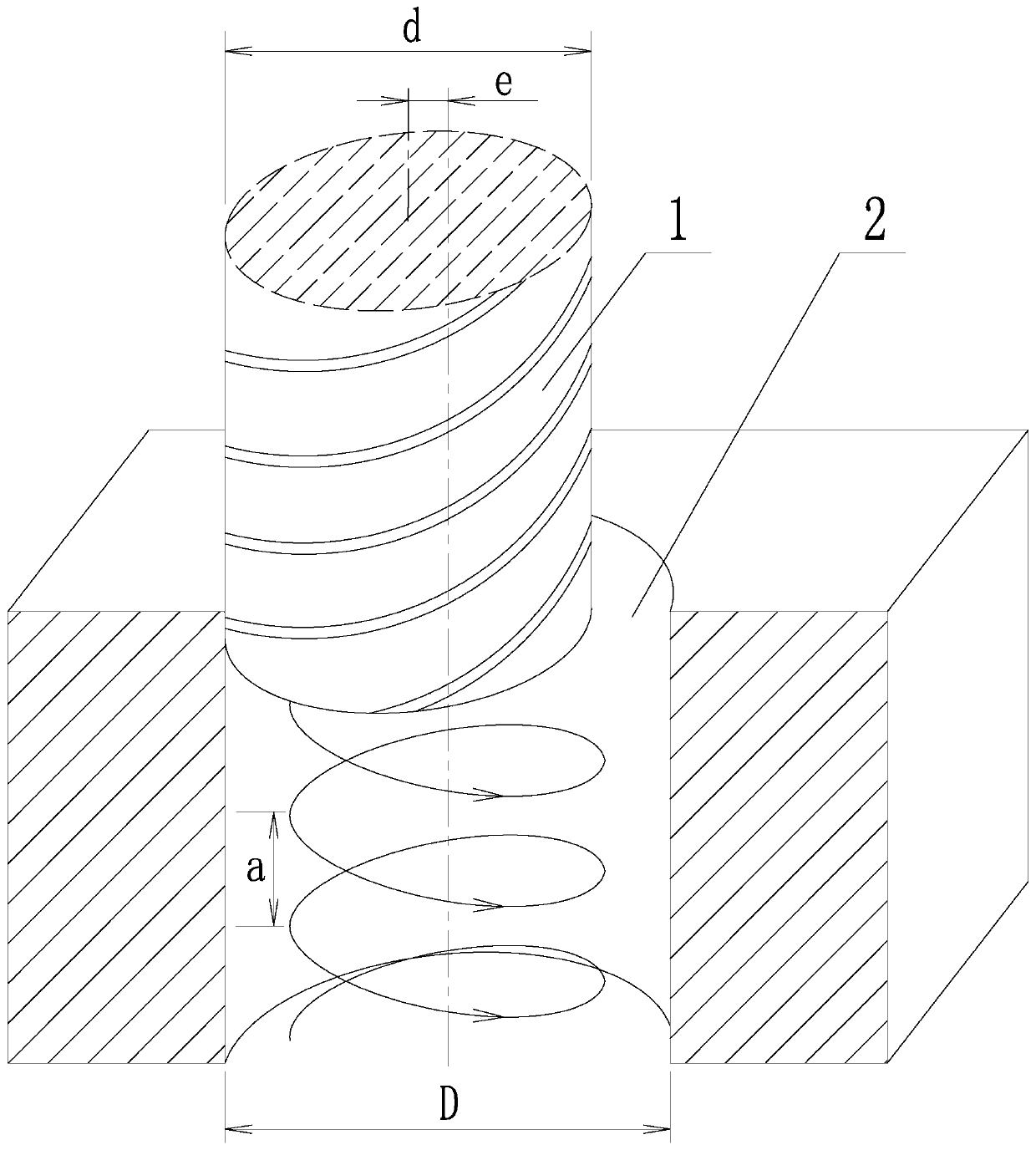
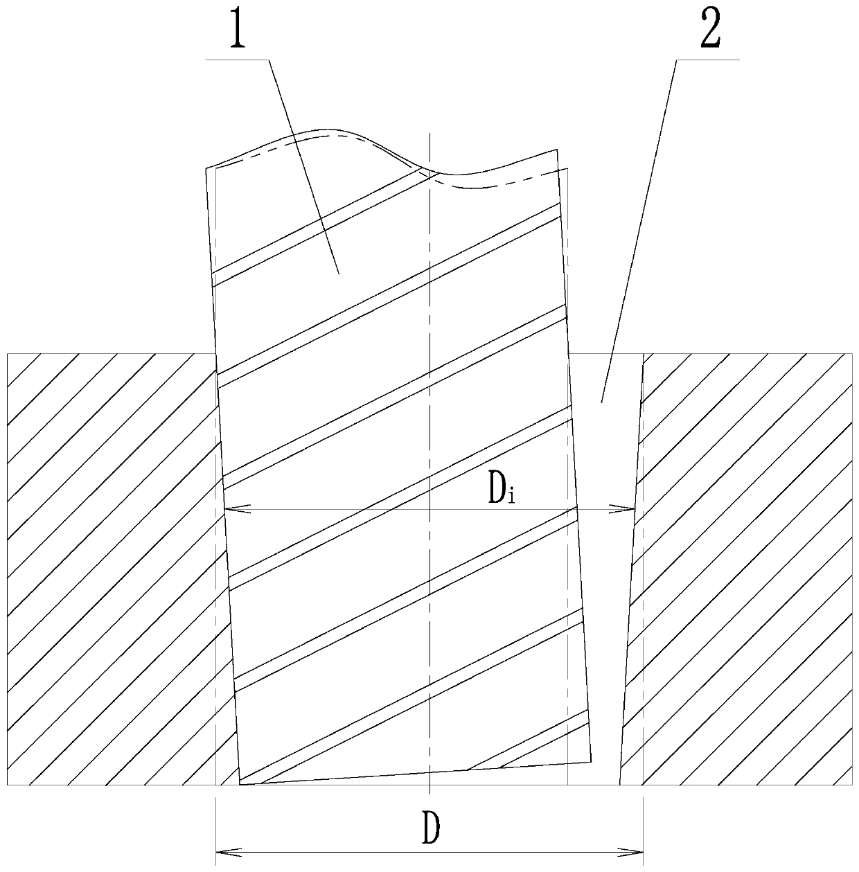
[0034] Step 2: Select the processing tool and set the processing parameters; in this embodiment, the tool is a solid carbide double-tooth end mill with a diameter of 4mm. The processing parameters include: the rotation speed of the tool is 3000r / min, the revolution speed of the tool is 10r / min, the eccentric distance between the tool axis and the assembly hole axis is 0.5mm, and the feed rate for one revolution of the tool is 0.5mm;

[0035] Step 3: Under the set processing parameters, use the selected processing to...


PUM


Abstract

Disclosed is a hole diameter error modified compensation method based on a screw milling hole. The hole diameter error modified compensation method comprises the steps of establishing a standard hole three-dimensional model for an assembly hole, selecting a machining tool, setting processing parameters, trial-manufacturing an assembly hole, detecting the aperture of the assembly hole, establishing a trial-manufacturing hole three-dimensional model according to the aperture detection result, comparing the trial-manufacturing hole three-dimensional model with the standard hole three-dimensional model, determining a hole diameter error of the assembly hole at different positions, setting compensation dosage according to the hole diameter error, synchronously modifying the eccentricity of the tool axis and the assembly hole axis in the processing parameters according to the compensation dosage, trial-manufacturing an assembly hole again under the modified processing parameters, establishing another trial-manufacturing hole three-dimensional model according to the aperture detection result, comparing the trial-manufacturing hole three-dimensional model with the standard hole three-dimensional model, and determining whether the aperture of the assembly hole at different positions meets the accuracy requirements or not, when the aperture meets the accuracy requirements, starting the formal manufacturing hole process of the assembly hole, otherwise, repeatedly adjusting the compensation dosage and synchronously modifying the processing parameters until the aperture meets the accuracy requirements.

Description

technical field [0001] The invention belongs to the technical field of helical milling hole making, in particular to an aperture error correction and compensation method based on helical milling hole making. Background technique [0002] At present, laminated materials made of carbon fiber composite materials and titanium alloys have been increasingly used in various types of modern aerospace vehicles. Maintenance costs have a positive effect. [0003] The laminated material mainly completes the assembly and connection of the carbon fiber composite material layer and the titanium alloy layer through bolts or rivets. Therefore, in the manufacturing process of the laminated material, a large number of assembly holes need to be processed on the carbon fiber composite material layer and the titanium alloy layer. In order to ensure the processing efficiency of the assembly hole, the integrated hole processing method is usually adopted, that is, the same tool and the same cutting...

Claims


Application Information

Patent Timeline
21 May 2019
Publication
CN106326596B
IPC
G06F17/50
CPC
G06F30/17; G06F30/20
Inventors
王奔; 马书娟