Supercharge Your Innovation With Domain-Expert AI Agents!

Steel pipe truss production line

A steel pipe truss and production line technology, applied in auxiliary devices, auxiliary welding equipment, welding/cutting auxiliary equipment, etc., can solve the problems of lack of mechanized production conditions, loss of supporting force, etc., to facilitate continuous and efficient production, and low leakage welding rate , the effect of high production efficiency

Pending Publication Date: 2019-05-10
SHANDONG ONE STAR CO NSTRUCTION TECH CO LTD
View PDF13 Cites 2 Cited by
  • Summary
  • Abstract
  • Description
  • Claims
  • Application Information

AI Technical Summary

Problems solved by technology

[0002] Prefabricated components of prefabricated buildings have been widely used in various building constructions such as residences, office buildings, and apartments in recent years. In order to improve the strength of prefabricated components, those skilled in the art have designed prefabricated components that are prefabricated with concrete components and steel trusses. This The trusses used in this kind of prefabricated components are mostly formed by welding the two sides of an upper chord steel bar with two bent steel bars at first. Because the steel pipe structure can further improve the load-bearing and compressive capacity of the truss, steel pipe truss products have begun to appear this year. This product welds bent steel bars on both sides of the steel pipe to form a truss structure, which effectively improves the load-bearing and compressive capacity. Since the welding position of the steel pipe and the steel bar is located at the arc top of the steel bar bend, when the steel bar provides support to the steel pipe, the steel bar bend will lose a part of the support force, so there is still room for improvement in the performance of the steel pipe truss. The upper ends of the straight steel bars on both sides of the bend of the steel bar are welded to the steel pipe, which can effectively increase the support force of the steel bar to the steel pipe. However, the existing truss production line cannot complete this welding, so this truss does not yet have mechanized production conditions.

Method used


Image

  • Steel pipe truss production line
  • Steel pipe truss production line
  • Steel pipe truss production line

Examples


Embodiment Construction

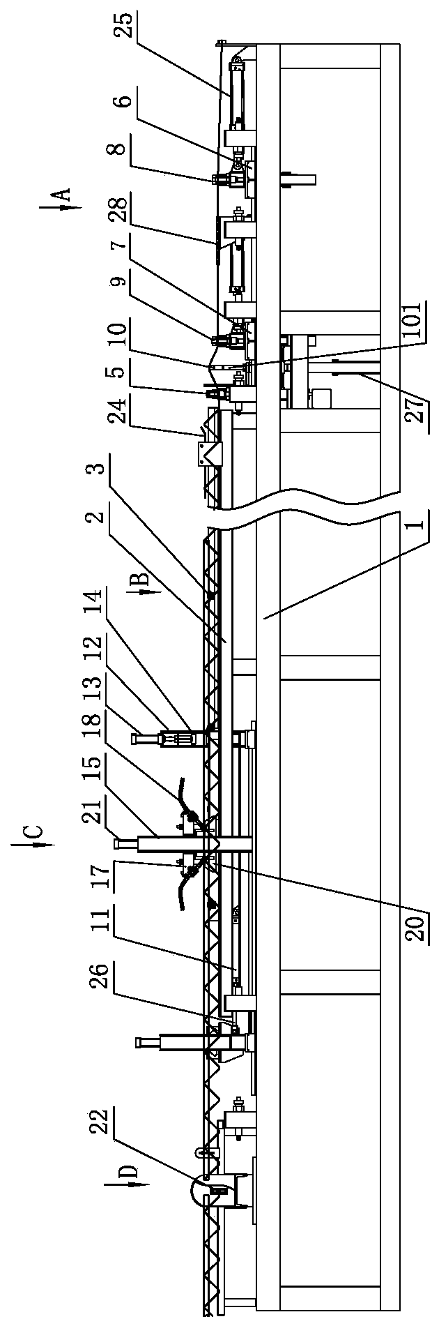
[0015] The steel pipe truss production line of the present invention comprises a frame 1, a steel pipe support 2 is installed on the frame 1, a plurality of steel pipe supporting wheels 3 are installed on the steel pipe support 2, steel bar guide grooves 4 are arranged on both sides of the steel pipe support 2 in the length direction, steel pipe support 2 One end is provided with steel bar bending and forming equipment 101, and the side of steel bar bending and forming equipment 101 away from the steel pipe support 2 is provided with a first slider 6, the first slider 6 is connected with the piston rod of the steel bar feeding cylinder 25 and can be placed in the steel bar feeding cylinder Driven by 25, it moves along the length direction of the frame 1, the first double-headed pneumatic steel bar clamp 8 is installed on the first slider 6, the movable frame 11 is installed on the frame 1, and the movable frame 11 is connected with the piston rod of the steel pipe drive cylinder...


PUM


Abstract

The invention discloses a steel pipe truss production line which comprises a rack. A steel pipe support is installed on the rack. Multiple steel pipe riding wheels are installed on the steel pipe support. Steel bar guide grooves are formed in the two sides of the length direction of the steel pipe support. A steel bar bending forming device is arranged at one end of the steel pipe support, and a first sliding block is arranged on the side, away from the steel pipe support, of the steel bar bending forming device. The first sliding block is connected with a piston rod of a steel bar feeding aircylinder and can move in the length direction of the rack under the drive of the steel bar feeding air cylinder. A first double-head pneumatic steel bar clamp is installed on the first sliding block,and a movable frame is installed on the rack. The movable frame is connected with a piston rod of a steel pipe driving air cylinder and can move in a reciprocating manner in the length direction of the rack under drive of the steel pipe driving air cylinder. A transverse moving frame is installed on the movable frame, and a downward pressing air cylinder is installed on the transverse moving frame. By means of the steel pipe truss production line, a steel pipe can be automatically welded to the two sides of the bending position of a steel bar, the production efficiency is high, and the lack welding rate is low; and continuous feeding and automatic unloading can be achieved, and continuous efficient production is facilitated.

Description

technical field [0001] The invention relates to a steel pipe truss production equipment, in particular to a steel pipe truss production line. Background technique [0002] Prefabricated components of prefabricated buildings have been widely used in various building constructions such as residences, office buildings, and apartments in recent years. In order to improve the strength of prefabricated components, those skilled in the art have designed prefabricated components that are prefabricated with concrete components and steel trusses. This The trusses used in this kind of prefabricated components are mostly formed by welding the two sides of an upper chord steel bar with two bent steel bars at first. Because the steel pipe structure can further improve the load-bearing and compressive capacity of the truss, steel pipe truss products have begun to appear this year. This product welds bent steel bars on both sides of the steel pipe to form a truss structure, which effectivel...

Claims


Application Information

Patent Timeline
Patent Type & Authority Applications(China)
IPC IPC(8): B23K37/00B23K37/053
CPCB21F1/00B21F1/02B21F11/00B21F15/00B21F23/00
Inventor 张波
Owner SHANDONG ONE STAR CO NSTRUCTION TECH CO LTD
Features
  • R&D
  • Intellectual Property
  • Life Sciences
  • Materials
  • Tech Scout
  • Unparalleled Data Quality
  • Higher Quality Content
  • 60% Fewer Hallucinations
Learn More