Electromechanical machining clamp for different workpieces

A workpiece fixture, electromechanical technology, applied in metal processing mechanical parts, manufacturing tools, metal processing equipment, etc., can solve the problems of difficult to achieve stable clamping, side slip of the clamping surface, etc., to improve practicability, facilitate clamping, Guaranteed effect of stability

Inactive Publication Date: 2019-05-10
SHANGHAI AIDENGBAO ELEVATOR JIANGSU
View PDF5 Cites 7 Cited by
  • Summary
  • Abstract
  • Description
  • Claims
  • Application Information

AI Technical Summary

Problems solved by technology

[0002] The tooling in the electromechanical field will use fixtures to fix the workpiece during processing to avoid movement of the workpiece during processing. The fixture needs to be made into a specific shape of fixture according to different parts. Traditional fixtures cannot be well fixed with different regular surfaces. For workpieces with complex clamping surfaces, using traditional fixtures will easily lead to side slip, and it is difficult to achieve stable clamping. Therefore, we propose a fixture for electromechanical processing that is suitable for different workpieces.

Method used


Image

  • Electromechanical machining clamp for different workpieces
  • Electromechanical machining clamp for different workpieces

Examples


Embodiment

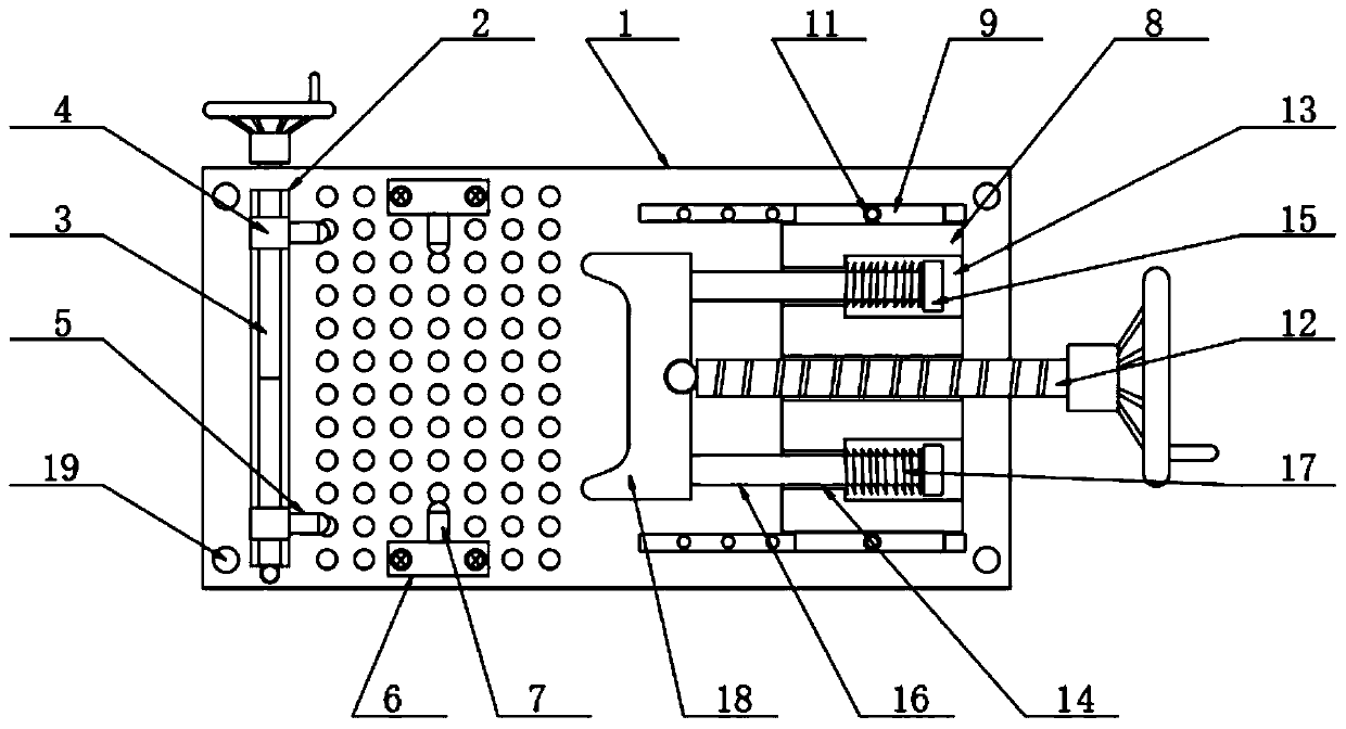
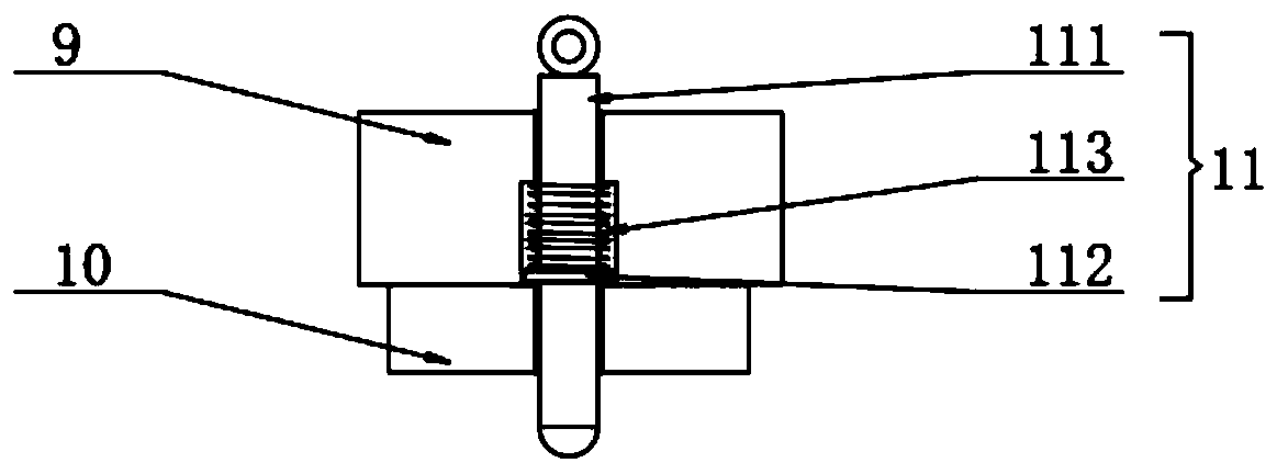
[0024] Embodiment: The fixture plate 1 is installed at a specified position through the mounting hole 19, and the two-way screw rod 3 is rotated according to the shape and size of the workpiece to drive the two groups of movable blocks 4 to approach or move away from each other to adjust the position, and at the same time, the adjusted position is adjusted by the screw. The receiving block 6 is fixedly connected with the top of the fixture plate 1. At the same time, according to the length of the workpiece, adjust the mounting block 8 to a suitable position, pull the insertion rod 111 upward, and the insertion rod 111 is separated from the socket upward, and pass the sliding block 10 and the horizontal sliding groove. Adjust the position of the mounting block 8, loosen the inserting rod 111, the return spring 113 drives the inserting rod 111 to reset and snap into the corresponding socket to fix the mounting block 8, and contact the left side of the workpiece with the round head...


PUM


Abstract

The invention discloses an electromechanical machining clamp for different workpieces in the technical field of electromechanics. The clamp comprises a clamp plate with screw connecting holes evenly formed in the top. The front end and the rear end of the outer wall of a two-way lead screw are symmetrically sleeved with movable blocks matching with a longitudinal sliding groove. The right sides ofthe two movable blocks are each provided with a first cuphead positioning pin. A screw rod is inserted in the middle of the right side of a mounting block. The left end of the screw rod penetrates through the mounting block and is movably connected with a clamping block through a rotating ball. The front end and the rear end of the right outer wall of the clamping block are each provided with a support rod. The left end of each support rod penetrates through the mounting block and is connected with a limit ring. The clamping block moves towards a workpiece by rotating the screw rod; as the diameter of a small hole is greater than the diameter of the support rods, when one end of the clamping block makes contact with the workpiece firstly, the clamping block tilts to the end making contactwith the workpieces firstly till the end not making contact with the workpiece makes contact with the workpiece, and the clamping operation is completed; thus, irregular planes of the workpiece can be clamped conveniently, and clamping is balanced and stable.

Description

technical field [0001] The invention relates to the field of electromechanical technology, in particular to a fixture suitable for different workpieces for electromechanical processing. Background technique [0002] The tooling in the electromechanical field will use fixtures to fix the workpiece during processing to avoid movement of the workpiece during processing. The fixture needs to be made into a specific shape of fixture according to different parts. Traditional fixtures cannot be well fixed with different regular surfaces. For workpieces with complex clamping surfaces, using traditional fixtures will easily lead to side slip, and it is difficult to achieve stable clamping. Therefore, we propose a fixture for electromechanical processing that is suitable for different workpieces. Contents of the invention [0003] The object of the present invention is to provide a fixture suitable for different workpieces for electromechanical processing, so as to solve the problem...

Claims


Application Information

Patent Timeline
Patent Type & Authority Applications(China)
IPC IPC(8): B23Q3/06
Inventor 李绥
Owner SHANGHAI AIDENGBAO ELEVATOR JIANGSU
Why Eureka
Try Eureka