
Milling device for laptop case

A notebook computer and shell technology, which is applied in the field of notebook computer shell milling device, can solve problems such as worker injury, waste can not be cleaned in time, equipment failure, etc., to avoid the loss of parts, the cleaning method is timely, and the cleaning effect is good.

Inactive Publication Date: 2019-05-10
重庆宇海精密制造股份有限公司
View PDF3 Cites 0 Cited by
  • Summary
  • Abstract
  • Description
  • Claims
  • Application Information

AI Technical Summary

Problems solved by technology

[0005] The purpose of the present invention is to provide a notebook computer shell milling device, which can avoid the problems of worker injury and equipment failure caused by the waste material not being cleaned up in time when the milling cutter device is milling the material head
[0007] Beneficial effects of the present invention: In the present invention, the waste material cleaning device cleans the waste material while the milling cutter device is milling the material head, which can solve the problems of worker injury and equipment failure caused by the waste material not being cleaned up in time when the milling cutter device is milling the waste material. Compared with the regular cleaning in the prior art, the cleaning method of the present invention is more timely

Method used


Image

  • Milling device for laptop case
  • Milling device for laptop case
  • Milling device for laptop case

Examples


Embodiment 1

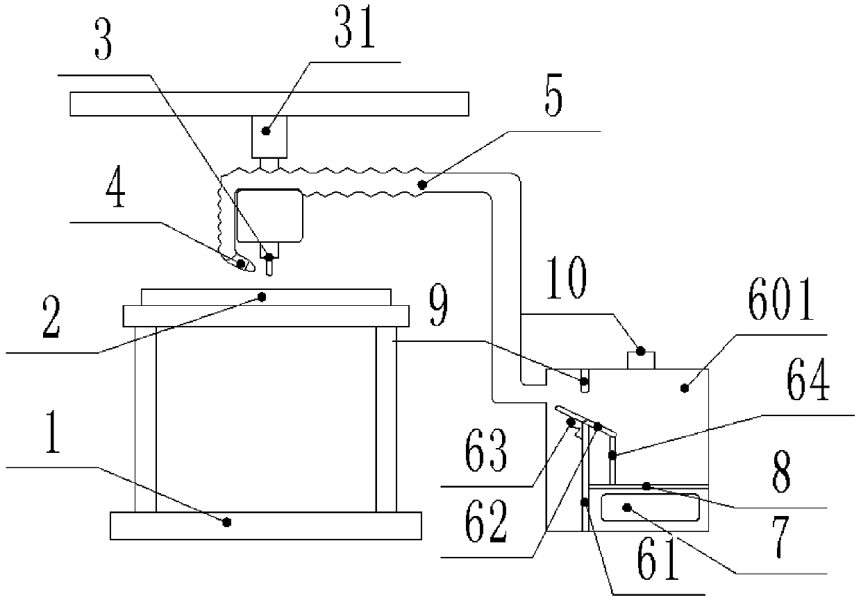
[0030] Such as figure 1 Shown: a notebook computer casing milling device, including a base 1, a placement table 2 for placing a notebook computer casing, a milling cutter device 3 for milling material heads, a mechanical arm 31 that drives the milling cutter device 3 to move, and a control milling cutter device 3, A control unit for the action of the mechanical arm 31. In this embodiment, the control unit can adopt OMRON's CP1H-XA40DR-A programmable controller, which is easy to program and stable in performance.

[0031] The upper end of the base 1 is welded and fixed with a bracket, and the top of the bracket is welded and fixed with the placement table 2 . The mechanical arm 31 is realized by the mechanical arm 31 in the prior art, and the milling cutter device 3 adopts the milling cutter device in the automatic milling device disclosed by the Chinese patent whose publication number is CN106273202A.

[0032] The notebook computer casing milling device in this embodiment al...

Embodiment 2

[0041] The only difference between this embodiment and the first embodiment is that the waste bin in this embodiment can classify waste materials and metals.

[0042] In modern industrial production, milling devices are mostly automatic devices, and the inspection of milling devices by maintenance personnel is generally a regular inspection. For industrial equipment, every component is critical, and most components are made of metal. In daily production, on the one hand, it is difficult for maintenance personnel to find the falling parts of the device, which leads to failures that cannot be eliminated; on the other hand, the dropped parts are mixed with waste and thrown away, which is also an economic loss.

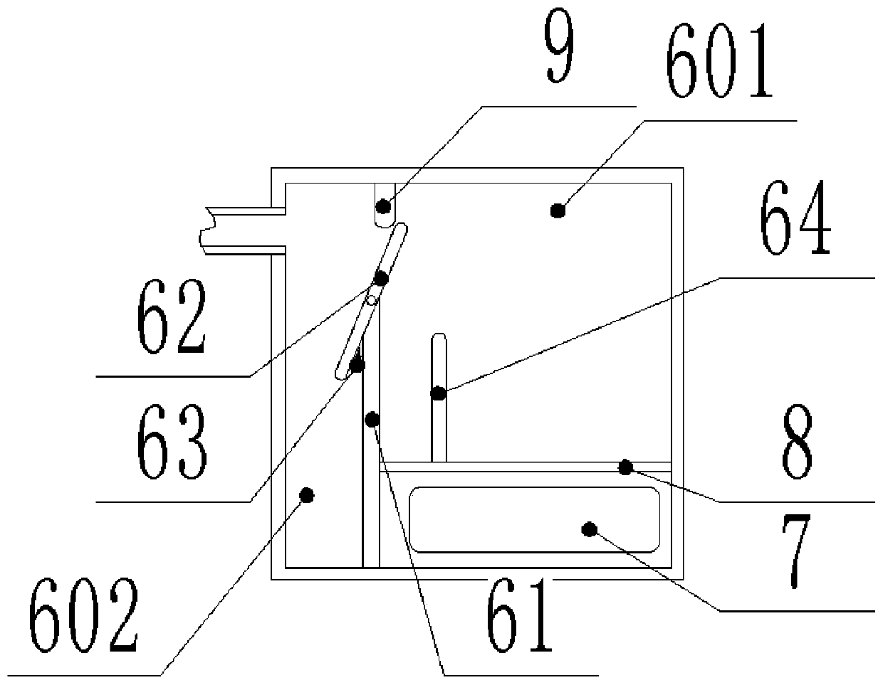
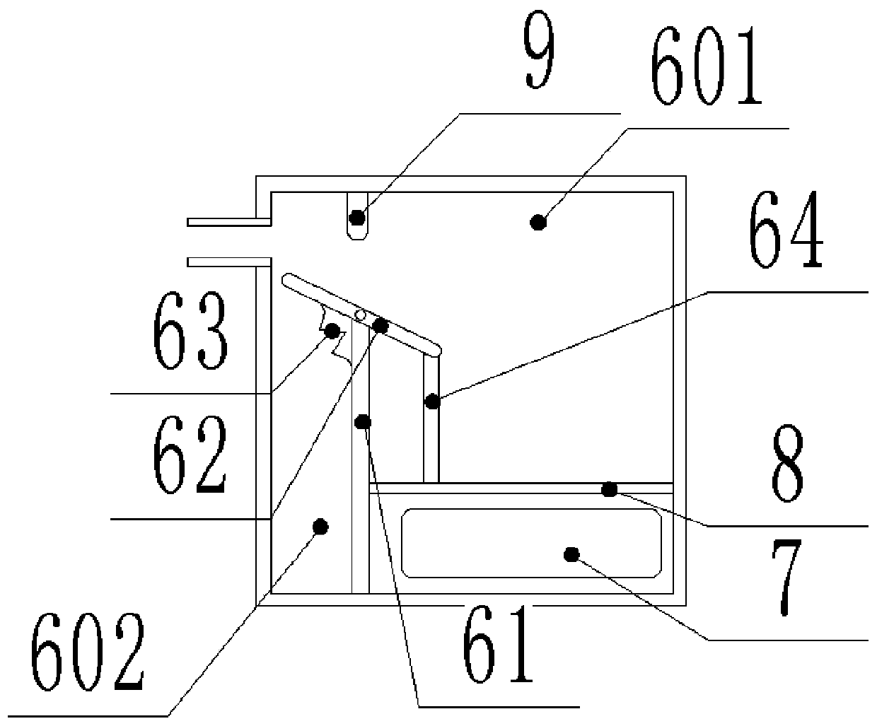
[0043] In this embodiment, a metal sensor capable of detecting the metal target of the adsorption head 4 is provided in the adsorption head 4, and the metal sensor is connected with the control unit signal; a prompt device 10 controlled by the control unit is fixed on the...


PUM


Abstract

The invention relates to the field of laptop manufacture and specifically relates to a milling device for a laptop case. The milling device comprises a placement table used to place the case, a milling cutter device for waste milling and a control unit used to control work of the milling cutter device as well as a waste cleaning unit used to clean waste, wherein a waste collection unit comprises asuction head firmly disposed on the milling cutter device and a waste box used to collect the waste; a vacuum device which can generate a negative pressure is disposed in the waste box; and an air pipe communicating with the waste box is firmly disposed on the suction head. The milling device for the laptop case disclosed by the invention can solve the problem that the waste cannot be cleaned intime during remain milling of the milling cutter device and thus workers get hurt and device failures take place.

Description

technical field [0001] The invention belongs to the field of notebook computer manufacturing, and in particular relates to a notebook computer shell milling device. Background technique [0002] After the notebook computer case is molded, the product taken out from the injection mold will have splinters. Therefore, when the product is taken out of the mold, the first thing to do is to remove the stubs. At present, the milling method of the material head of the notebook computer shell is to use a milling device to mill the material. [0003] For example, the Chinese patent whose publication number is CN106273202A discloses a kind of automatic milling device, which includes: a support; a feed slide rail, which is fixed in the support; a feed slide table, which slides and is located on the feed slide rail; material slide rail, which is fixed on the top of the feeding slide; a support plate, which is slidably arranged on the take-up slide rail; a compression cylinder, which is ...

Claims


Application Information

Patent Timeline
Patent Type & Authority Applications(China)
IPC IPC(8): B29C45/38B29L31/34
Inventor 张大斌刘国际
Owner 重庆宇海精密制造股份有限公司
Learn More