

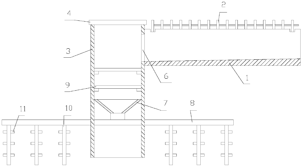
Drainage ditch structure
A technology of drainage ditches and drainage channels, applied in the direction of side ditches/curbs, etc., can solve the problems of waste and stagnant water that cannot be used effectively, and achieve the effects of convenient reuse, simple structure and cost saving
- Summary
- Abstract
- Description
- Claims
- Application Information
AI Technical Summary
Problems solved by technology
Method used
Image

Examples
Embodiment Construction
[0014] It should be noted that, in the case of no conflict, the embodiments in the present application and the features in the embodiments can be combined with each other; the technical solutions in the embodiments of the present invention will be described below in conjunction with the drawings in the embodiments of the present invention Clearly and completely described, it is obvious that the described embodiments are only some of the embodiments of the present invention, not all of them. Based on the embodiments of the present invention, all other embodiments obtained by persons of ordinary skill in the art without making creative efforts belong to the protection scope of the present invention.
[0015] In the description of the present invention, it should be understood that the orientation or positional relationship indicated by the terms "upper", "lower", "front", "rear", "left" and "right" are based on those shown in the accompanying drawings. Orientation or positional ...
PUM
 Abstract
Description
Claims
Application Information