Rolling friction walkingjacking and pushing device for bridge segment installation

A technology of rolling friction and jacking devices, which is applied in the direction of bridges, bridge construction, erection/assembly of bridges, etc. It can solve the problem of increasing the horizontal thrust at the top of bridge piers or temporary piers, which is prone to discrete jitter, and affects the smooth jacking construction of bridges and other problems, to achieve the effect of increasing the area, increasing the diameter of the cylinder body and improving the smoothness

CN109736212APending Publication Date: 2019-05-10郭正兴 +2
0 Cites 4 Cited by

Patent Information

Authority / Receiving Office
CN · China
Current Assignee / Owner
Publication Date
2019-05-10

Smart Images

  • Figure 1
    Figure 1
  • Figure 2
    Figure 2
  • Figure 3
    Figure 3
Patent Text Reader

Abstract

The invention discloses a rolling friction walking jacking and pushing device for bridge segment installation. The rolling friction walking jacking and pushing device for the bridge segment installation comprises a groove type travelling track tray (1), a long ram jacking and pushing hydraulic jack (2), a rolling mobile platform car (3), a steel plate box (4),a steel tube cup type sliding shoe (5), a transversely rectifying hydraulic jack (6), and a lifting hydraulic jack (7), whereinthe groove type travelling track tray is combinedly welded by circumferential side plates and a bottom plate, the hydraulic jack is fixed to the end plate, in the direction orthogonal to that of the jacking and pushing, of the tray, the rolling mobile platform car is placed in the tray and connected with a pinof the jacking and pushing hydraulic jack, the steel plate box is placed and fixed on the rolling mobile platform car, the steel tube cup type sliding shoe is placed in the steel plate box and connected with a pin of the transversely rectifying hydraulic jack which is fixed to the side plate, in the direction orthogonal to that of the jacking and pushing, of the steel plate box, and the lifting hydraulic jack is placed in the steel tube cup type sliding shoe. According to the rolling friction walking jacking and pushing device for the bridge segment installation, horizontal thrust of a bridgepier or the top of a temporary buttress pier and local stress when lifting a beam body are substantially decreased during the jacking and pushing installation process of the bridge, smooth and rapidjacking and pushing can be achieved.
Need to check novelty before this filing date? Find Prior Art

Description

technical field

[0001] The invention relates to a rolling-friction walking shoe pushing device installed in bridge segments, which belongs to the field of civil engineering bridge construction and installation equipment. Background technique

[0002] In the construction of civil engineering bridges, the installation of prefabricated concrete bridges and steel bridges for various cross-line and river-cross highways and municipal engineering needs to be installed without interrupting traffic and navigation. In recent years, jacking devices have been installed on bridge piers or temporary piers, and new bridges are fabricated in sections. Continuous pulling or exchange jacking constructions have gradually increased. The main advantage is that the traffic environment below the newly built bridges and traffic conditions are minimally affected. The main method of the known walking pushing device for the installation and construction of bridge sections is to place the hydraulic ja...

Examples

Embodiment Construction

[0021] The present invention will be further described below in conjunction with the accompanying drawings and specific embodiments.

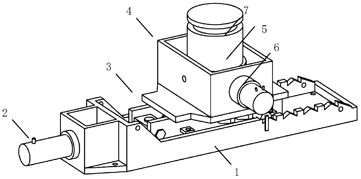
[0022] Such as figure 1 As shown, the trough-shaped walking track tray 1, the long-stroke jacking hydraulic jack 2, the mobile platform car 3, the steel plate box 4, the steel cup-shaped sliding shoe 5, the deviation-correcting hydraulic jack 6, and the center-lifting hydraulic jack 7 are assembled into a suitable Rolling friction type walking push-up device installed on the bridge section push-up.

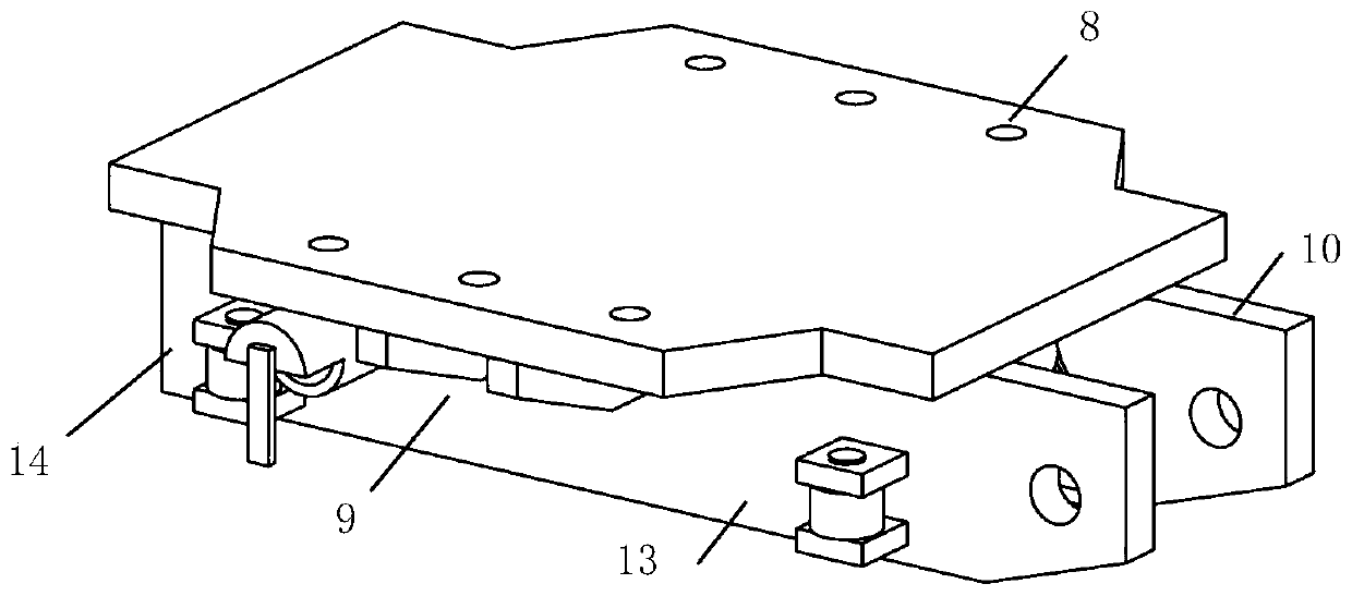
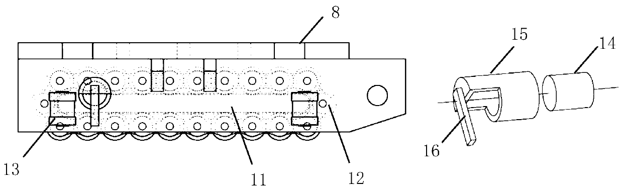
[0023] The realization of the function of longitudinal pushing and installation of the bridge girder body: the platform plate 8 of the mobile platform vehicle 3 is welded with two parallel vertical support plates 10 along the longitudinal pushing direction, and the outer side of the joint is welded with a triangular stiffener 9 for reinforcement. A pair of lateral limit rollers 13 are arranged on the outside of each vertical support plate 10, and ...