Supercharge Your Innovation With Domain-Expert AI Agents!

a gear pump

A gear pump and gear cavity technology, applied in the direction of pumps, pump components, rotary piston pumps, etc., can solve the problem of inconvenient addition of lubricating fluid, and achieve the effect of compact structure, stable output flow, and guaranteed reliability.

Active Publication Date: 2020-04-17
CHINA PETROLEUM & CHEM CORP +2
View PDF12 Cites 0 Cited by
  • Summary
  • Abstract
  • Description
  • Claims
  • Application Information

AI Technical Summary

Problems solved by technology

[0004] The purpose of the present invention is to provide a gear pump to solve the problems in the prior art that it is inconvenient to add lubricating fluid to the bearings of the driving shaft and the driven shaft.

Method used


Image

  • a gear pump
  • a gear pump
  • a gear pump

Examples


Embodiment Construction

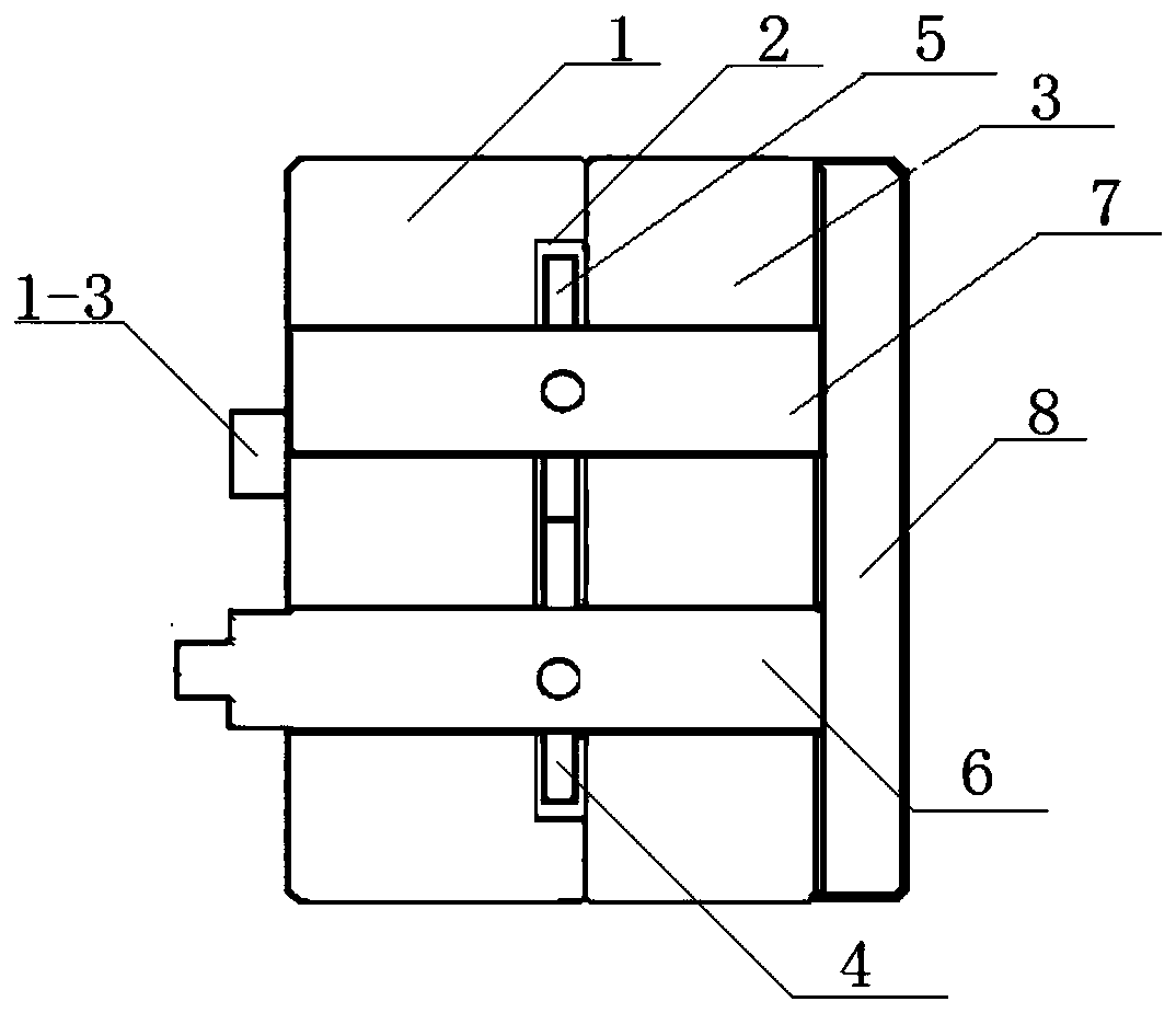
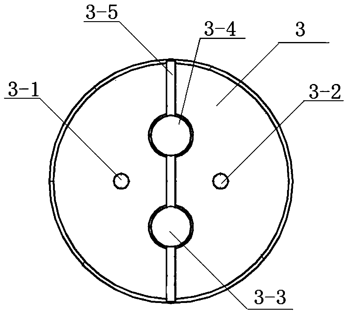
[0026] According to the above technical solution, this embodiment discloses a gear pump, which includes an upper pump cover 1, a hollow gear cavity 2 and a lower pump cover 3, and a driving gear 4 meshing with each other is arranged inside the hollow gear cavity 2. The driven gear 5, the driving gear 4 is sleeved on the driving shaft 6, the driven gear is sleeved on the driven shaft 7, and the lower pump cover 3 is also provided with an oil inlet 3 -1 and the oil outlet 3-2, the oil inlet 3-1 and the oil outlet 3-2 are respectively located on both sides of the straight line formed by the centers of the driving shaft 6 and the driven shaft 7.

[0027] Such as Figure 1-4 As shown, the overall structure of the gear pump disclosed in this embodiment is similar to the structure of the gear pump in the prior art, including an upper pump cover 1, a hollow gear cavity 2 and a lower pump cover 3 connected in sequence, wherein the upper pump cover 1 and the shape of the lower pump cov...


PUM


Abstract

The invention discloses a gear pump. One side, away from a hollow gear cavity, of a lower pump cover is provided with a sealing cover used for sealing a first driving shaft bearing hole and a first driven shaft bearing hole, the lower pump cover is further provided with an oil drainage groove, the oil drainage groove is arranged along a straight line formed by connecting a circle center of the first driving shaft bearing hole and a circle center of the first driven shaft bearing hole, and the oil drainage groove communicates with the first driving shaft bearing hole and the first driven shaftbearing hole. According to the gear pump, a sealing channel formed by arranging the oil drainage groove and the sealing cover, so that cooling oil in the hollow gear cavity passes through the bearingholes when the cooling oil is discharged out of the outer side of the gear pump so as to provide lubrication for the bearing holes, the problem that a lubricating liquid is not convenient to add fromthe outer side of the gear pump to the bearing holes is avoided, so that the working reliability of the gear pump is improved.

Description

technical field [0001] The invention relates to a hydraulic actuator, in particular to a gear pump. Background technique [0002] As the core liquid boosting component of the hydraulic actuator, the gear pump can realize high-pressure and stable delivery of hydraulic oil, and has the characteristics of low-pulsation bidirectional work and compact structure. Existing high-pressure gear pumps usually use a floating side plate structure to increase the outlet pressure of the gear pump. For example, the prior art discloses a floating side plate of a gear pump that can withstand ultra-high pressure. The power condition improves the pressure resistance level of the hydraulic gear pump. The prior art discloses a compact high-flow low-pulsation gear pump, which reduces the flow pulsation of the gear pump by superimposing the instantaneous oil discharge of three large helix-angle gear pairs; in addition, the gear pump in the prior art The bearings of the driving shaft and the drive...

Claims


Application Information

Patent Timeline
Patent Type & Authority Patents(China)
IPC IPC(8): F04C2/18F04C15/00
Inventor 田中山许开富赖少川王文廷徐燕萍齐琛杨文罗鹏
Owner CHINA PETROLEUM & CHEM CORP
Features
  • R&D
  • Intellectual Property
  • Life Sciences
  • Materials
  • Tech Scout
  • Unparalleled Data Quality
  • Higher Quality Content
  • 60% Fewer Hallucinations
Learn More