Combined piston sealing element

A technology for combining pistons and seals, which is applied to engine seals, engine components, mechanical equipment, etc., can solve problems such as shortened life of seal rings, inability to double seal protection between piston and cylinder wall, large gaps, etc., and achieve improved sealing performance Effect

Inactive Publication Date: 2019-05-10
LANZHOU UNIVERSITY OF TECHNOLOGY +1
View PDF5 Cites 1 Cited by
  • Summary
  • Abstract
  • Description
  • Claims
  • Application Information

AI Technical Summary

Problems solved by technology

[0004] Aiming at the deficiencies of the prior art, the present invention provides a combined piston seal, which solves the problem of the cylinder sealing structure and its sealing material proposed in the above-mentioned background technology. Due to the large contact surface between the sealing ring and the cylinder body, under pressure, the friction Excessive resistance, excessive frictional resistance will easily cause premature wear and failure of the sealing ring, resulting in shortened life of the sealing ring, and because it cannot provide double sealing protection between the piston and the cylinder wall, resulting in the piston working with the cylinder wall. There is a large gap between the cylinder walls, which affects the sealing performance between them and other disadvantages

Method used


Image

  • Combined piston sealing element
  • Combined piston sealing element
  • Combined piston sealing element

Examples


Embodiment Construction

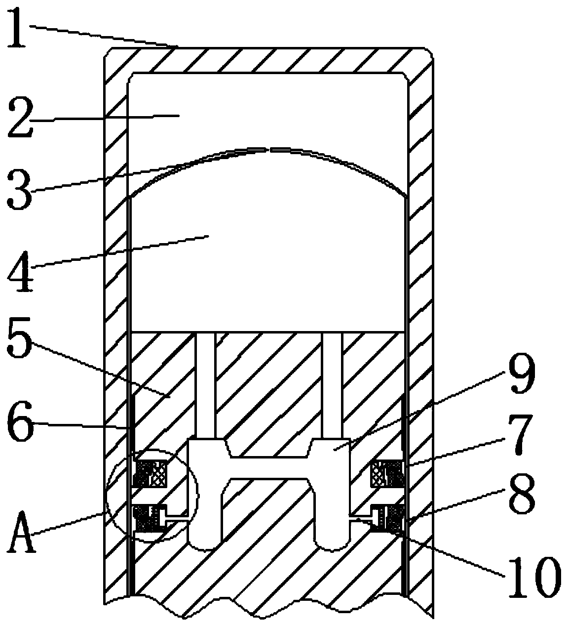
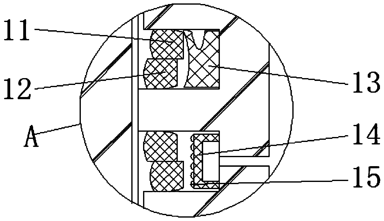
[0021] The following will clearly and completely describe the technical solutions in the embodiments of the present invention with reference to the accompanying drawings in the embodiments of the present invention. Obviously, the described embodiments are only some, not all, embodiments of the present invention.

[0022] In the description of the present invention, unless otherwise stated, the meaning of "plurality" is two or more; the terms "upper", "lower", "left", "right", "inner", "outer" , "front end", "rear end", "head", "tail", etc. indicate the orientation or positional relationship based on the orientation or positional relationship shown in the drawings, and are only for the convenience of describing the present invention and simplifying the description, rather than Nothing indicating or implying that a referenced device or element must have a particular orientation, be constructed, and operate in a particular orientation should therefore not be construed as limiting ...


PUM


Abstract

The invention discloses a combined piston sealing element, which relates to the technical field of sealing rings, specifically a cylinder, a hot cavity and a through hole, wherein a convex top cavityis arranged in the cylinder, a piston is connected in the convex top cavity, a micro small hole is formed in the top end of the convex top cavity, the hot cavity is arranged above the convex top cavity, a guide ring is arranged on the outer wall surface of the piston; an upper combined seal element is arranged below the guide ring; a lower combined seal element is arranged below the upper combinedseal element, the upper combined seal element and the lower combined seal element are respectively arranged in the outer wall surface of the piston, and the through hole is formed in the top end of the piston. According to the combined piston seal element, the cross section of a floating ring is a semi-rectangular barrel surface type under a working state, the lower edge of the working surface ofthe outer circle of the floating ring is in contact with the cylinder wall, and the lower edge of the inner circle of the ring is in contact with a C-shaped compensation bulge, so that the sealing performance is good, and the semi-rectangular angle is 7 degrees according to the standard.

Description

technical field [0001] The invention relates to the technical field of seal rings, in particular to a combined piston seal. Background technique [0002] With the development of science and technology, domestic and foreign attach great importance to the development of sealing technology, and have achieved results, such as the "sock seal" device of Philips in the Netherlands and the new sliding sealing device of Sweden's United Stirling Engine Company. The latter has low cost and long life. [0003] The cylinder sealing structure and its sealing material disclosed in the Chinese Invention Patent Application Publication No. CN102269273B, the cylinder sealing structure and its sealing material, although the above-mentioned cylinder sealing structure is not only simple in structure, but also has a plastic compensation function, which realizes small frictional resistance and solves the problem of The cylinder can delay the aging of the seal under the condition of high temperatur...

Claims


Application Information

Patent Timeline
Patent Type & Authority Applications(China)
IPC IPC(8): F16J15/16F16J15/3232
Inventor 杨东亚李伟涛田松熊新稳李瑞红
Owner LANZHOU UNIVERSITY OF TECHNOLOGY
Why Eureka
Try Eureka