Biomass combustor and biomass fuel furnace

A biomass fuel and burner technology, which is applied in the direction of combustion equipment, solid heating fuel, solid fuel combustion, etc., can solve the problems of adding fuel, occupying the biomass fuel space in the furnace, and short burning time of the heating furnace, etc., to ensure that The effect of burning time and increasing the intake area

Pending Publication Date: 2019-05-10
山东正信德环保科技发展有限公司
View PDF0 Cites 2 Cited by
  • Summary
  • Abstract
  • Description
  • Claims
  • Application Information

AI Technical Summary

Problems solved by technology

[0003] The purpose of the present invention is to provide a biomass burner, aiming at solving the problem that the gas collector of the biomass burner in the prior art will occupy the space of the biomass fuel in the furnace, resulting in a short burning time of the heating furnace and the need for frequent refueling. fuel technical issues

Method used


Image

  • Biomass combustor and biomass fuel furnace
  • Biomass combustor and biomass fuel furnace
  • Biomass combustor and biomass fuel furnace

Examples


Embodiment Construction

[0025] In order to make the technical problems, technical solutions and beneficial effects to be solved by the present invention clearer, the present invention will be further described in detail below in conjunction with the accompanying drawings and embodiments. It should be understood that the specific embodiments described here are only used to explain the present invention, not to limit the present invention.

[0026] Please also refer to Figure 1 to Figure 4 , the biomass burner provided by the embodiment of the present invention will now be described.

[0027] A biomass burner comprising:

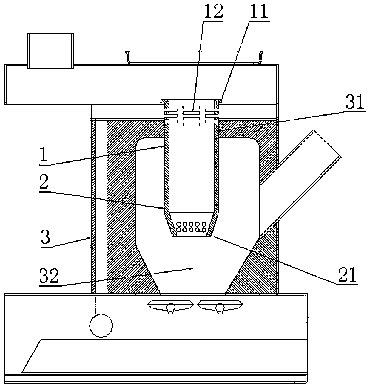
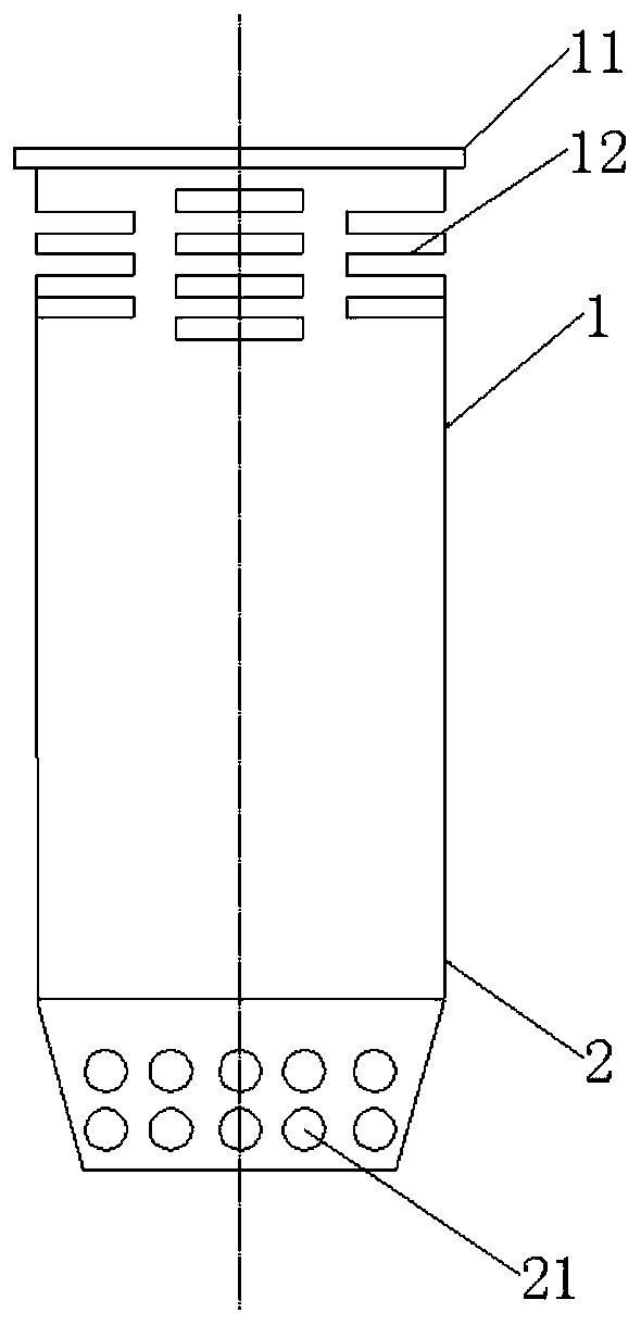
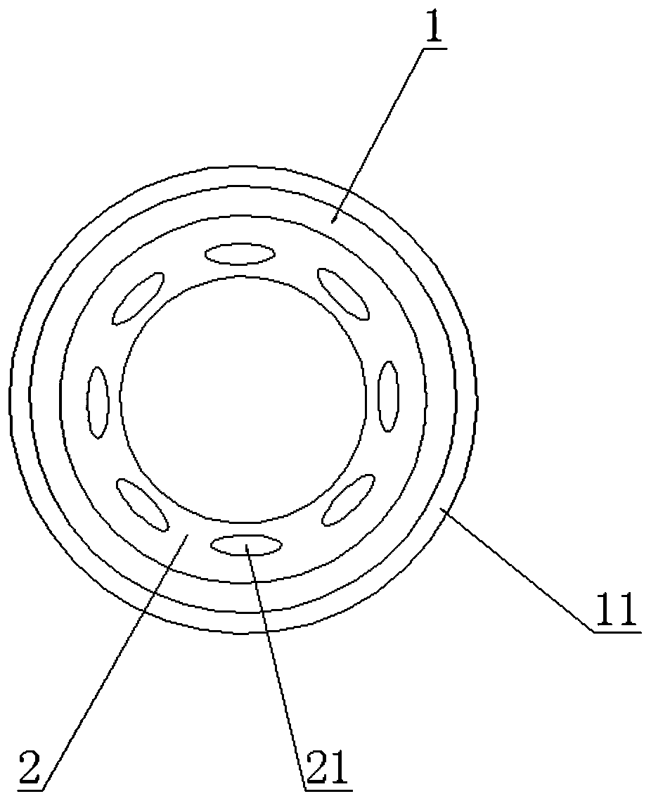
[0028] The combustion tube 1 is used to be arranged in the furnace mouth 31, and the combustion end is used for burning the combustible gas in the combustion tube 1; and

[0029] Gas collector 2, the gas outlet end communicates with the intake end of combustion cylinder 1, the inlet end gradually shrinks from top to bottom and is used to insert into the biomass fuel pile in the fu...


PUM


Abstract

The invention provides a biomass combustor and a biomass fuel furnace, and belongs to the field of furnace accessories. The biomass combustor comprises a combustion barrel and a gas collection barrel.The combustion barrel is used for being arranged in a furnace opening, and the combustion end is used for combustion of combustible gas in the combustion barrel. The gas outlet end of the gas collection end communicates with the gas inlet end of the combustion barrel, the gas inlet end of the gas collection barrel gradually shrinks from top to bottom and is used for being inserted into a biomassfuel assembly in a hearth, and gas collection holes are formed in the side wall of the gas inlet end. The gas inlet end of the gas collection barrel can be inserted into the biomass fuel assembly moredeeply, meanwhile, the space of biomass fuel in a furnace cavity cannot be occupied too much, combustible gas at the deep position of the biomass fuel assembly can be collected easily, and the gas collection holes formed in the gas inlet end of the gas collection barrel guarantees sufficiency of the collected combustible gas. The biomass combustor is adopted by the biomass fuel furnace, the combustible at the deep position of the biomass fuel assembly in the hearth can be guided out from the combustion barrel, meanwhile, the space of the biomass fuel in the furnace cavity cannot be occupied too much by the gas collection barrel, and it is guaranteed that combustion time is long.

Description

technical field [0001] The invention belongs to the technical field of stove accessories, and more specifically relates to a biomass burner and a biomass fuel furnace. Background technique [0002] The existing biomass burner has a cylindrical structure, the lower end of which is a gas collector, and the upper end is a combustion tube. When the existing biomass burner is in use, the lower end of the gas collector is the air intake end, which needs to be buried in the biomass fuel pile, so that the gas collector can export the combustible gas generated in the biomass fuel pile, and put it on the upper end of the combustion cylinder. The combustion end burns. However, if the air intake end of the gas collector is buried in the biomass fuel pile, it will occupy the space of the biomass fuel in the furnace, reduce the amount of biomass fuel filled in the furnace, and lead to a short burning time of the heating furnace, requiring frequent refueling. Fuel has brought great incon...

Claims


Application Information

Patent Timeline
Patent Type & Authority Applications(China)
IPC IPC(8): F23B90/06F24B1/08
Inventor 李娜陈劼
Owner 山东正信德环保科技发展有限公司
Why Eureka
Try Eureka