
Low-temperature non-stop heat pump air-conditioning system and control method thereof

A heat pump air-conditioning and low-temperature technology, which is applied in the direction of refrigerators, compressors, refrigeration components, etc., can solve problems such as low pressure, unit failure to operate normally, and difficulty in absorbing heat in the air-cooled evaporator, achieving the effect of simplifying the structure of the unit

Pending Publication Date: 2019-05-10
GUANGDONG HIWAVE TECH
View PDF0 Cites 4 Cited by
  • Summary
  • Abstract
  • Description
  • Claims
  • Application Information

AI Technical Summary

Problems solved by technology

[0003] At present, among the solutions to environmental pollution caused by coal burning in the north, air source heating is becoming an optimal solution, but at the same time, facing the phenomenon of low ambient temperature in winter in the north, the scope of use of compressors has become a limitation of air source heat pumps. Important factors: the lower the ambient temperature, the more difficult it is for the air-cooled evaporator to absorb heat, the lower the low-pressure pressure of the compressor, and the compressor evaporation temperature exceeds the designed operating range of the compressor and there is a limit or protection (the evaporation temperature is too low to form enough The low-pressure evaporating gas cannot reach the low pressure limit for compressor startup), and the low-pressure pressure of the heat pump circuit is too low, which eventually leads to the failure of the unit to operate normally at low ambient temperature

Method used


Image

  • Low-temperature non-stop heat pump air-conditioning system and control method thereof
  • Low-temperature non-stop heat pump air-conditioning system and control method thereof

Examples


Embodiment Construction

[0021] The present invention is further described in conjunction with the following examples.

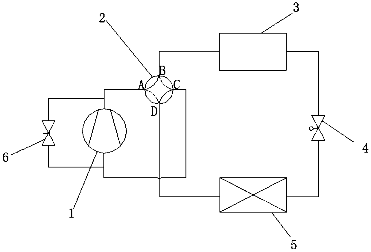
[0022] A specific embodiment of a low-temperature non-stop heat pump air-conditioning system of the present invention, such as figure 2 As shown, it includes a condenser 3, a throttling device 4, an evaporator 5, a compressor 1 and a four-way valve 2, and the outlet of the compressor 1 passes through the first group of interfaces A, B of the four-way valve 2, the condenser 3, The throttling device 4, the evaporator 5, and the second group of ports D and C of the four-way valve 2 are connected to the inlet of the compressor 1 to form a heat pump circuit. The heat pump air-conditioning system also includes high and low pressure for adjusting the pressure difference of the heat pump circuit. Bypass device 6 , one end of the high and low pressure bypass device 6 communicates with the outlet of the compressor 1 , and the other end of the high and low pressure bypass device 6 communicate...


PUM


Abstract

The invention relates to the technical field of air conditioners, in particular to a low-temperature non-stop heat pump air-conditioning system. The low-temperature non-stop heat pump air-conditioningsystem comprises a condenser, a throttling device, an evaporator and a compressor. An outlet of the compressor is connected with an inlet of the compressor through the condenser, the throttling device and the evaporator in sequence to form a heat pump loop. The low-temperature non-stop heat pump air-conditioning system is characterized by further comprising a high and low-pressure bypass device used for regulating the differential pressure of the heat pump loop; compared with the prior art, the high and low-pressure bypass device is connected with the two working ends of the compressor in parallel; the differential pressure of the two ends of the compressor is balanced through the high and low-pressure bypass device, and it is ensured that the compressor still can operate normally under the condition of the excessive low environment temperature. The problem that the cost is increased due to the fact that other heating equipment needs to be additionally input for auxiliary heating is solved. The unit structure is simplified. The invention further provides a control method of the low-temperature non-stop heat pump air-conditioning system.

Description

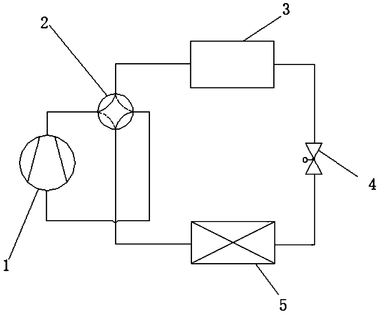
technical field [0001] The invention relates to the technical field of air conditioning, in particular to a low-temperature non-stop heat pump air conditioning system and a control method thereof. Background technique [0002] The traditional air energy heat pump heating / heating air conditioning system is mainly composed of compressor 1, evaporator 5, condenser 3, throttling device 4, and four-way valve 2, as shown in the attachment figure 1 As shown in the traditional air energy heat pump system, when the system is heating, the high-pressure and high-temperature refrigerant heat discharged by the compressor 1 is released to the use side in the condenser 3, and the refrigerant becomes a low-temperature and low-pressure two-phase state after being throttled by the throttling device 4 , absorb the heat in the air in the evaporator 5 to become a superheated gas, and then return to the compressor 1 for compression, thus completing the heating cycle. [0003] At present, among t...

Claims


Application Information

Patent Timeline
IPC IPC(8): F25B13/00F25B41/00F25B49/02F25B41/40
Inventor 赵应升吕东建陈锡保蒙棠豪
Owner GUANGDONG HIWAVE TECH
Learn More