Winding of electrical machine with switch-over mechanism

A switching mechanism and motor winding technology, applied in the shape/style/structure of winding conductors, circuits, electric switches, etc., can solve the problems of complex switching methods, many control switches, and many lead-out wires, and achieve simplified unit structure, contact Reliable, Simple Effects

Active Publication Date: 2008-12-10
上海星之辰电气传动技术有限公司
View PDF0 Cites 17 Cited by
  • Summary
  • Abstract
  • Description
  • Claims
  • Application Information

AI Technical Summary

Problems solved by technology

[0005] However, the number of turns of the conventional permanent magnet motor winding coil cannot be changed at present. Although it is known that the number of winding turns can be changed after changing the series-parallel connection mode of the sub-windings of the motor, because there are too many lead-out wires and too many control switches for each phase sub-winding, The switching method is very complicated, and it is difficult to practically promote and apply it on the motor

Method used


Image

  • Winding of electrical machine with switch-over mechanism
  • Winding of electrical machine with switch-over mechanism
  • Winding of electrical machine with switch-over mechanism

Examples


Embodiment 1

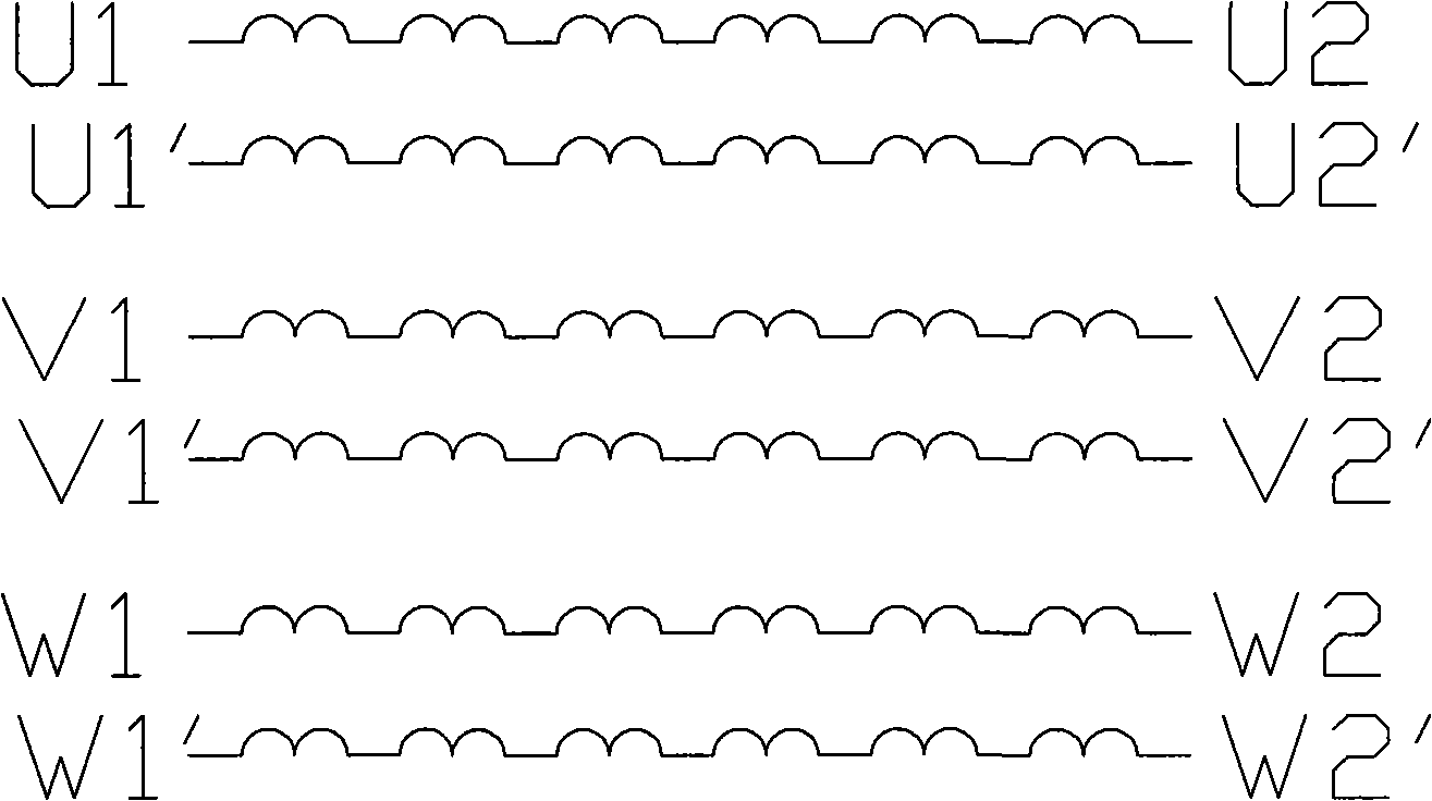
[0021] Embodiment 1 of the motor winding with switching mechanism of the present invention includes an iron core and a winding wound on the iron core and a switching mechanism. Each phase of the three-phase winding has 2 identical sub-windings and is wound in parallel, such as figure 1 As shown, U phase is U 1 -U 2 and U 1 ’-U 2 ’ Two sub-windings are wound in parallel, and the V phase is V 1 -V 2 and V 1 '-V 2 ’ Two sub-windings are wound in parallel, and the W phase is W 1 -W 2 and W 1 ’-W 2 ’ Two sub-windings are wound together.

[0022] u 1 -U 2 , V 1 -V 2 , W 1 -W 2 respectively with U 1 ’-U 2 ’, V 1 '-V 2 ’, W 1 ’-W 2 'After the parallel connection, output according to the conventional delta or star connection. When the same current is passed through the outside, the influence of the armature reaction is ignored. When the torque output of the parallel delta connection is 1, the torque output of the parallel star connection is 1.73.

[0023] u 1 -...

Embodiment 2

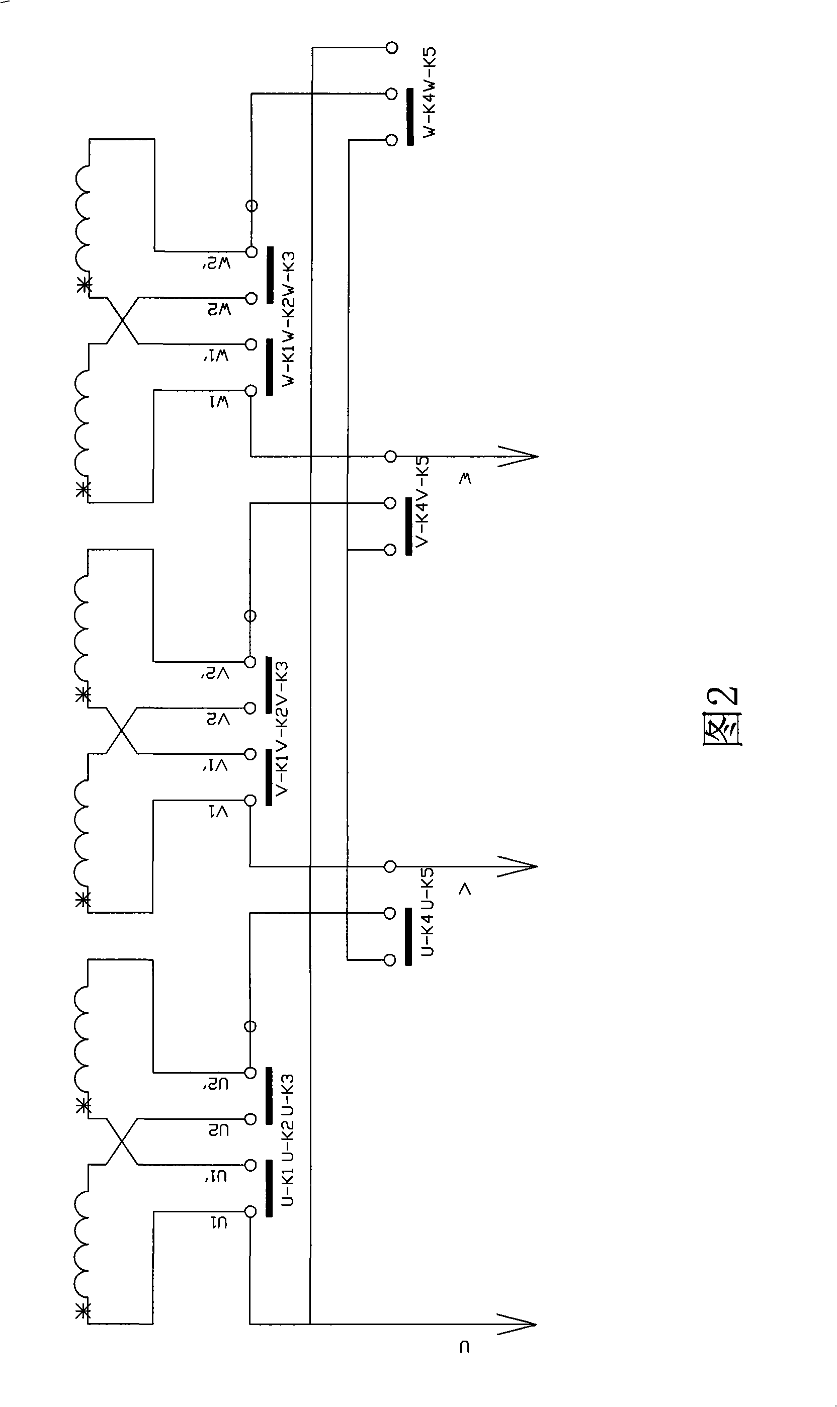
[0044] This example is a simplified structure of Example 1. Same as Example 1, each phase winding has 2 sub-windings, but the three phases are kept in a star connection, and the switching mechanism has only two gears, changing the series-parallel connection of the sub-windings. The different wiring methods of the sub-windings are shown in Figure 6. U in the picture1 , V 1 , W 1 U, V, W are the final leads of the three-phase winding, U 2 ’, V 2 ’, W 2 ’ Connected. Each phase winding has K 1 to K 3 Three touch bridges. UK 1 The sub-winding terminal U corresponding to the U phase 1 , U 1 ’, UK 2 Corresponding endpoint U 1 ’, U 2 , UK 3 Corresponding endpoint U 2 , U 2 ’; VK 1 The terminal point V of the sub-winding corresponding to the V phase 1 , V 1 ’; VK 2 Corresponding terminal V 1 ’, V 2 , VK 3 Corresponding terminal V 2 , V 2 ’; WK 1 Corresponding to the sub-winding terminal W of phase W 1 , V 1 ’, WK 2 Corresponding endpoint W 1 ’, W 2 ;WK 3...

Embodiment 3

[0054] This example is another simplified structure of Example 1. Same as Example 1, each phase winding has 2 sub-windings, but its three phases remain in delta connection. The different wiring methods of sub-windings are as follows: Figure 7 shown. Similar to example 2, in the figure U 1 , V 1 , W 1 U, V, W are the final leads of the three-phase winding, but U 2 ’ with V 1 connected, V 2 ’ with W 1 connected, W 2 ’ with U 1 connect. Same as Example 2, there are two connection methods of series and parallel for sub-windings, and the switching mechanism is the same as Example 2.


PUM


Abstract

The invention relates to a machine winding with a switching mechanism. Each phase of a three-phase winding is parallel winded by two to four ways of the same separate winding. Each separate winding can be in series connection, or in series-parallel connection, or all in parallel connection via synchronously switching by a switch block of the switching mechanism. Three-phase can take a shape of star or can be changed into triangle to be connected. When the number of windings and connection mode of each phase winding change and outside is accessed the same current, moment or rotate speed generated by an armature can be changed in wide range. Contact bridges and connecting sheets on each switch layer block of the switching mechanism form the switch. A plurality of switch layers are connected in order and each layer of cams going through an axis of rotation therein leads each layer of the contact bridges to move, and each switch turns on and off synchronously. Different shapes of the cams of each switch layer are designed according to the logical relationship of end-to-end connection of each separate winding. The axis of rotation drives the cams of each switch layer to rotate synchronously and switches off different connection combinations of the separate winding such as star-shaped series connection, triangle series connection, star-shaped parallel connection and triangle parallel connection, so as to realize to regulate the twisting moment and the rotate speed of a motor in the wide range. The switching mechanism has the advantages of reliable contact, energy-saving, easy operation.

Description

(1) Technical field [0001] The invention relates to a motor winding structure, in particular to a motor winding with a changeable winding coil number of each phase. (2) Background technology [0002] In many application fields of electric motors, the starting and accelerating phases of the motor require the motor to output a large torque but the required speed is low, while the high-speed operation phase requires a small torque but requires a high motor speed. In order to achieve a relatively wide range of torque and speed regulation, usually apply overload current to the motor or increase the excitation current when running at low speed and high torque, and perform field weakening control on DC motor or synchronous motor when running at high speed and low torque, while for Asynchronous motors are over-frequency controlled. Commonly used motors include series excitation motors, independent excitation synchronous motors, hybrid excitation motors, and asynchronous motors. Th...

Claims


Application Information

Patent Timeline
IPC IPC(8): H02K3/28H01H19/50
CPCH02K3/28
Inventor 吕虹
Owner 上海星之辰电气传动技术有限公司
Why Eureka
Try Eureka