A serpentine channel cross-flow air-to-air heat exchanger structure for aero-engine

An aero-engine and heat exchanger technology, applied in indirect heat exchangers, lighting and heating equipment, etc., to reduce the length of the channel, increase the degree of turbulence, and strengthen the heat exchange effect.

Inactive Publication Date: 2020-07-14
NORTHWESTERN POLYTECHNICAL UNIV
View PDF1 Cites 0 Cited by
  • Summary
  • Abstract
  • Description
  • Claims
  • Application Information

AI Technical Summary

Problems solved by technology

Liu Yinze published a paper titled "Flow Heat Exchange Performance Analysis of Primary Surface Heat Exchangers of Aeroengines" on aero-engines, in which 4 different structural forms of primary surface heat exchangers were proposed, but the present invention involves using There are no papers or patents published on the structure of the meandering channel for impinging heat exchange on the primary heat exchange surface.

Method used


Image

  • A serpentine channel cross-flow air-to-air heat exchanger structure for aero-engine
  • A serpentine channel cross-flow air-to-air heat exchanger structure for aero-engine
  • A serpentine channel cross-flow air-to-air heat exchanger structure for aero-engine

Examples


Embodiment

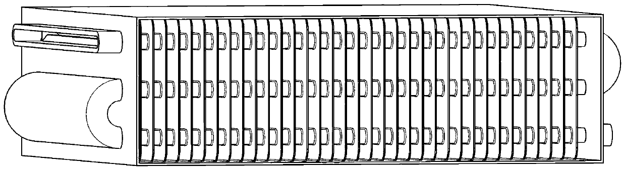
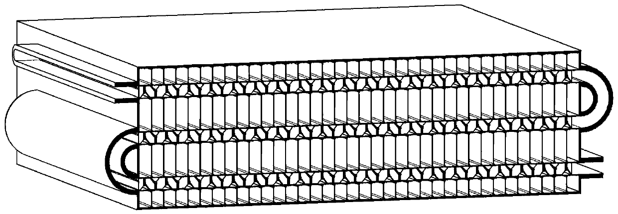
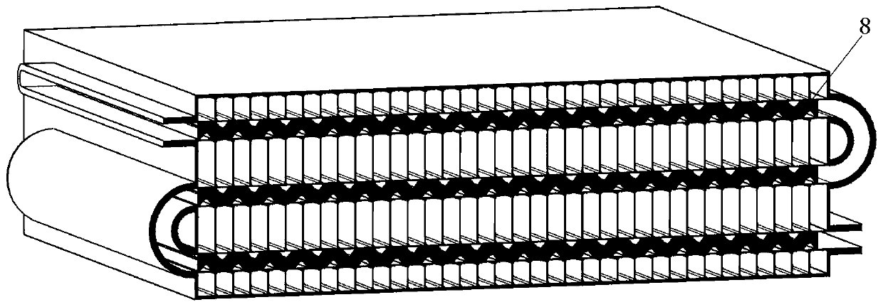
[0037] This implementation example is a common tube-fin heat exchanger. The outer wall of the heat exchange channel adopts the prior art.

[0038] There are discontinuous fork-row ribs arranged in the cold flow channel, the distance D between adjacent ribs is 5.5mm, the distance between the outermost two ribs is 5.25mm from the wall of the cold flow channel, and the projection distance of the front and rear rows of ribs in the flow direction is 6mm, a total of 5 A row of straight fins, each fin forms a round chamfer with a radius of 0.5mm with the wall of the heat flow channel, and the thickness of each fin is 0.5mm. The outermost two ribs of the second row of fork ribs are respectively 2.5mm away from the wall surface of the cold flow channel. The length of the cold channel is 205mm, the width is 200mm, and the height is 62mm. The cold flow channel is divided into 4 small cold flow channels by the hot flow channel, including two 14mm high cold flow channels and two 7mm high...


PUM


Abstract

The invention provides a meandering channel cross flow air-air heat exchanger structure of an aeroplane engine. Extending triangular fins are arranged in a heat flow channel of a heat exchanger. The triangular fins arranged in the heat flow channel in a staggered mode. A folding line type heat flow outer channel is formed by the outer surfaces of the triangular fins. Cross flow heat transfer is adopted for the heat flow outer channel and a cold flow channel of the heat exchanger. The triangular fins have certain thicknesses and are hollow inside. A heat flow inner channel is formed by series connection of the hollow inner channels of the triangular fins. The heat flow inner channel is arranged in an N shape and conducts downstream and countercurrent heat exchange with fluid in the cold flow channel of the heat exchanger sequentially. The heat flow inner channel is separated from the heat flow outer channel by partitioning plates. The partitioning plates are arranged on two sides of theheat flow channel. An inlet of the heat flow inner channel is formed in one side of one of the partitioning plates. The lateral side of the other partitioning plate is a sealed surface. The heat exchanging effect is effectively improved, and weight of the heat exchanger is greatly reduced.

Description

technical field [0001] The invention relates to the technical field of aero-engine heat exchangers, in particular to a meandering channel cross-flow air-to-air heat exchanger structure for aero-engines. Fluid direction, providing impact heat transfer effect on the primary heat transfer surface. Background technique [0002] The cold and hot flows of the aero-engine heat exchanger come from the low-temperature gas in the external duct and the bleed air of the high-pressure compressor respectively. The high-temperature and high-pressure hot gas passes through a flat channel to exchange heat with the cold air. The cold air channel is a rectangular channel, and the hot gas channel is connected to the The cold air passages intersect in a cross shape, and the hot air passages repeatedly shuttle through the cold air passages. Usually, parallel straight fins are arranged in the cold and hot air passages to enhance heat exchange, but this will increase the weight of the heat exchang...

Claims


Application Information

Patent Timeline
Patent Type & Authority Patents(China)
IPC IPC(8): F28D21/00
Inventor 刘存良刘锋苏云亮张灵俊王钦钦
Owner NORTHWESTERN POLYTECHNICAL UNIV
Why Eureka
Try Eureka