
Stage structure

A sub-stage and seed technology, applied in the aerospace field of solid launch vehicles, can solve the problems of the landing tail of the rocket body, the complex structure of the sub-stage, and the heavy weight, etc., to achieve good aerodynamic stability, simplify the structure, reduce space and effect of weight

Pending Publication Date: 2019-05-10
BEIJING XINGJI RONGYAO SPACE TECH CO LTD
View PDF8 Cites 1 Cited by
  • Summary
  • Abstract
  • Description
  • Claims
  • Application Information

AI Technical Summary

Problems solved by technology

[0007] Therefore, the technical problem to be solved by the present invention is that the structure of the existing sub-level structure is complicated, the weight is large, and the landing tail of the rocket body is easily damaged by impact.

Method used


Image

  • Stage structure
  • Stage structure
  • Stage structure

Examples


Embodiment 1

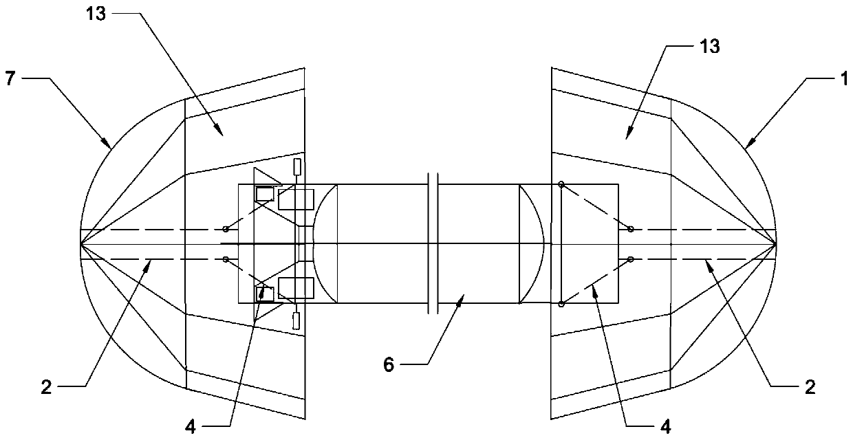
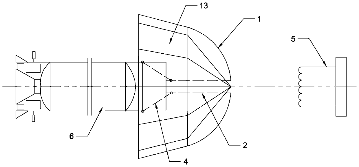
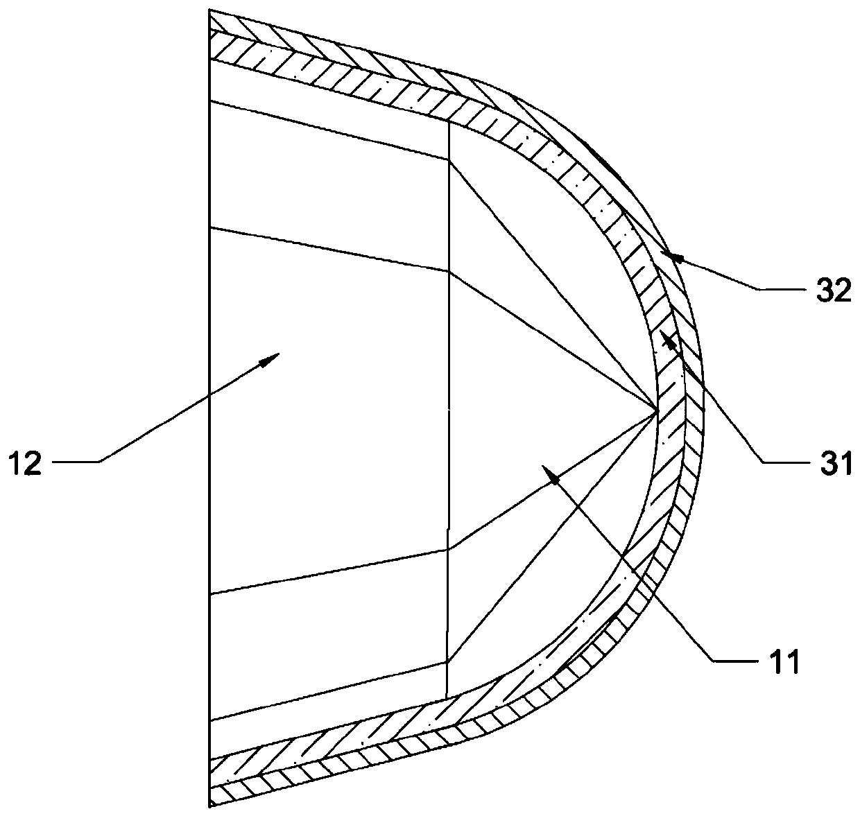
[0056] This embodiment provides a sub-level structure, such as Figure 1 to Figure 8 Shown, comprise arrow body, be located at the pneumatic deceleration mechanism on the head of arrow body, be located at the pneumatic anti-collision mechanism on the arrow body afterbody. Wherein, the pneumatic deceleration mechanism includes a pneumatic head 1 , a multi-layer heat insulation layer 31 , an anti-ablation layer 32 , and a rigid connector 2 .

[0057] Specifically, the pneumatic head 1 is an inflatable second air bag that can be transformed between a folded state and an expanded state; The windward side of the airbag gradually increases toward the leeward side of the second airbag; the leeward side of the second airbag encloses a recessed area, and when the second airbag is deployed, the recessed area is set outside the head of the arrow body. Specifically, as image 3 and Figure 4 As shown, the second airbag includes a head 11 and an inverted cone 12 disposed on the end of t...

Embodiment 2

[0090] This embodiment provides a sub-level structure, and the only difference with the sub-level structure provided in Embodiment 1 is that the structure of the first airbag is different, and the pneumatic anti-collision mechanism in this embodiment can also be an airbag of other shapes, such as a U-shaped Airbags, S-shaped airbags, V-shaped airbags or other shaped airbags can be used. The airbags can be placed on the tail of the rocket body to prevent the tail of the rocket body from directly colliding with the ground when it lands.


PUM


Abstract

The invention discloses a stage structure comprising a rocket body, a pneumatic reduction mechanism and a pneumatic anti-collision mechanism. The pneumatic reduction mechanism comprises a pneumatic head and an ablation resisting layer. The pneumatic head is a second gas bag capable of being shrunk and spread. The second gas bag covers the head of the rocket body. The pneumatic anti-collision mechanism is provided with a first gas bag capable of being shrunk and spread. The first air bag covers the tail of the rocket body. After being inflated, the second gas bag is of a symmetrical structureand has good pneumatic stability. The outer wall of the second gas bag is provided with an ablation resisting layer, so that the second gas bag cannot be burned during flying aloft at high temperature. The second gas bag can reduce the speed of the rocket body at high temperature in high altitude; besides, during landing in low altitude, the second gas bag can achieve a buffering function on the rocket body; the second gas bag has the foldable capacity, so that the occupied space on the rocket body and the weight of the second gas bag can be reduced. Meanwhile, the first gas bag can achieve the flexible buffering function on the tail when the tail of the rocket body lands, and therefore the rocket body is prevented from being damaged.

Description

technical field [0001] The invention relates to the aerospace technology field of solid launch vehicles, in particular to a sub-stage structure. Background technique [0002] During the different ballistic return processes of the sub-stage structure of the solid launch vehicle, after the sub-stage structure is separated from the upper pole structure, the sub-stage structure will continue to fly high outside the atmosphere due to inertia for a period of time, and then return to the earth's atmosphere inside, and land on the ground. The current sub-level structure mainly includes a rocket body, a front section structure located at the head of the rocket body, and a rear section structure located at the rear section of the rocket body. The front section structure mainly includes deceleration device, navigation guidance and control system, attitude control system and other equipment. When the sub-structure returns to the earth's atmosphere and lands downward, the deceleration ...

Claims


Application Information

Patent Timeline
Patent Type & Authority Applications(China)
IPC IPC(8): F42B10/48F42B10/00
Inventor 不公告发明人
Owner BEIJING XINGJI RONGYAO SPACE TECH CO LTD
Learn More