Liquid collection device

A liquid collection and collection container technology, which is applied in liquid treatment, sampling devices, packaging, etc., can solve the problems of complex body fluid collection operations and achieve the effect of simplifying operations

Pending Publication Date: 2019-05-10
LINKGEN BIOTECH SHANGHAI CO LTD
View PDF6 Cites 1 Cited by
  • Summary
  • Abstract
  • Description
  • Claims
  • Application Information

AI Technical Summary

Problems solved by technology

[0003] The purpose of the present invention is to provide a liquid collection device, to a certain extent, to solve the technical problem of cumbersome body fluid collection operations in the prior art

Method used


Image

  • Liquid collection device
  • Liquid collection device
  • Liquid collection device

Examples


Embodiment 1

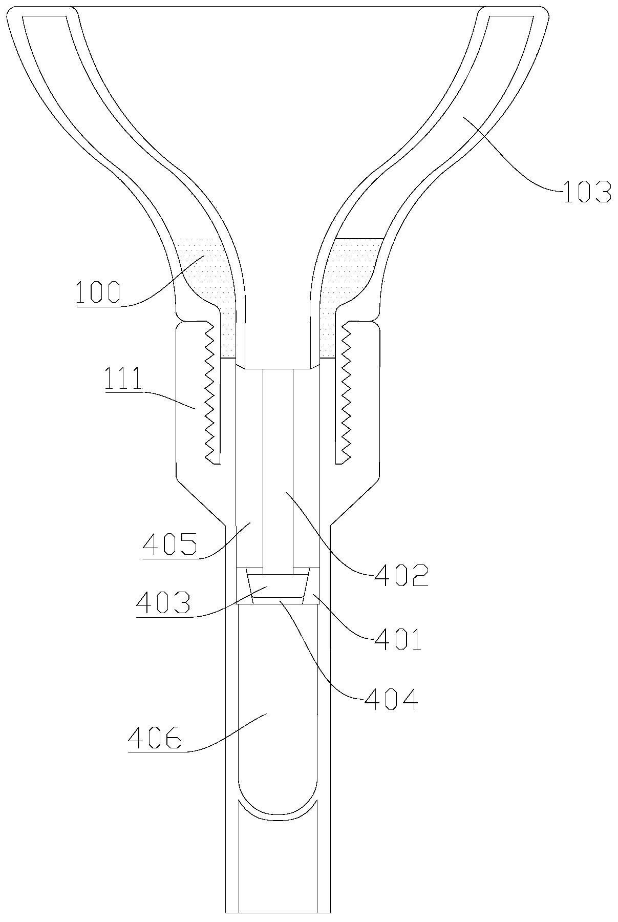
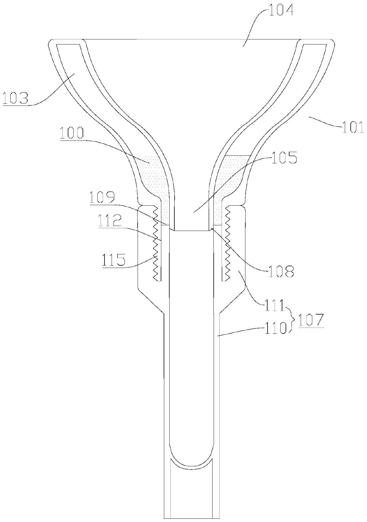
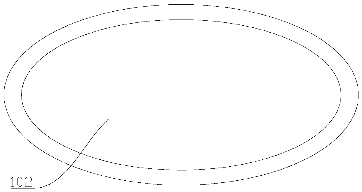
[0035] see figure 2 , image 3 , Figure 12 , Figure 13 and Figure 14 As shown, the embodiment of the present invention provides a liquid collection device, which includes a collection container 101, and the collection container 101 is provided with a flow guide cavity 102 for guiding the collected body fluid. At least one interlayer cavity 103 for storing the preservation solution 100 is provided on the wall of the collection container 101, the interlayer cavity is arranged around the diversion cavity, and the interlayer cavity extends along the axial direction of the diversion cavity, that is, The axial direction of the interlayer cavity is basically parallel to the axial direction of the diversion cavity; the diversion cavity has an inlet 104 and an outlet 105, and the diameter of the inlet is larger than that of the outlet; the cross-sectional diameter of the diversion cavity is from the inlet to the outlet. The direction of exit gradually decreases.

[0036] Speci...

Embodiment 2

[0048] The second embodiment also provides a liquid collection device. The liquid collection device in this embodiment describes the relative rotation between the storage container 107 and the collection container 101, so that the interlayer cavity 103 and the There is another implementation solution for the connection or disconnection between the cavities of the storage container 107, and the other technical solutions of the first embodiment also belong to this embodiment, and will not be described again.

[0049] see Figure 4 and Figure 5 Shown, in this embodiment, the quantity of the interlayer cavity is one; The housing part of collection container 101 has internal thread, and storage container 107 has the external thread that matches with external thread; The insertion part of collection container is U-shaped structure 201, An annular groove 112 is formed between the shell part of the collection container 101 and a side of the U-shaped structure, and the liquid outlet ...

Embodiment 3

[0051] The third embodiment also provides a liquid collection device, and the liquid collection device in this embodiment describes another implementation scheme for connecting or disconnecting the interlayer cavity 103 and the cavity of the storage container 107 , the other technical solutions of Embodiment 1 also belong to this embodiment, and will not be described again.

[0052] see Figure 6 , Figure 7 and Figure 11 Shown, shown, shown, in this embodiment, there are multiple interlayer cavities, and the multiple interlayer cavities 103 are separated by an isolation layer 106, and the length of the isolation layer is along the length of the guide cavity 102 Axially extending; the isolation layer is cylindrical. The liquid outlet 109 of the interlayer cavity 103 is close to the outlet 105 of the collection container 101, and away from the inflow port 104 of the collection container 101. During use like this, the liquid outlet 109 can be conducted so that the liquid in ...


PUM


Abstract

The invention provides a liquid collection device. The liquid collection device comprises a collection container; the collection container is provided with a diversion cavity for performing diversionof collected body liquid; at least one interlayer cavity used for storing preservation liquid is arranged on the wall of the collection container; the interlayer cavity is arranged around the diversion cavity; furthermore, the interlayer cavity extends along the axial direction of the diversion cavity; the cross section of the interlayer cavity is annular; the diversion cavity is provided with aninflowing hole and an outflowing hole; and the aperture of the inflowing hole is greater than that of the outflowing hole. Due to the diversion cavity, diversion of collected liquid (such as saliva, blood or urine) is conveniently carried out; because the at least one interlayer cavity is arranged, the preservation liquid can be stored in the collection container; therefore, the dual functions ofcollection container for performing diversion of liquid and storage of the preservation liquid are realized; therefore, when the device is used, a pipe for individually storing the preservation liquidis saved; and the operation is simplified.

Description

technical field [0001] The invention relates to the technical field of liquid collection, in particular to a liquid collection device. Background technique [0002] Existing bodily fluid collection devices, especially for the funnel of the split-type saliva collector in the way of collecting saliva, collection tubes, containers with preservation fluid, etc., are stored separately. When using, spit saliva first, then open the container cover of the container containing the preservation solution, pour the preservation solution into the collection tube along the funnel, then remove the funnel, and then screw on the separately provided cover, the overall operation is more complicated. Contents of the invention [0003] The purpose of the present invention is to provide a liquid collection device to solve the technical problem of complicated body fluid collection operations in the prior art to a certain extent. [0004] The invention provides a liquid collection device, which ...

Claims


Application Information

Patent Timeline
Patent Type & Authority Applications(China)
IPC IPC(8): G01N1/20
CPCG01N1/20A61B10/0051B67C2011/20B67C11/02
Inventor 殷中奇徐李青潘瑾
Owner LINKGEN BIOTECH SHANGHAI CO LTD
Why Eureka
Try Eureka