Lens laminating system and method

A technology for laminating systems and lenses, applied in the directions of installation, optics, instruments, etc., can solve the problems of high labor dependence, large labor demand and low efficiency in the lens lamination process, so as to reduce labor intensity, improve accuracy and The effect of efficiency

Pending Publication Date: 2019-05-10
WUHAN RAYCUS FIBER LASER TECHNOLOGY CO LTD
View PDF0 Cites 6 Cited by
  • Summary
  • Abstract
  • Description
  • Claims
  • Application Information

AI Technical Summary

Problems solved by technology

[0006] The purpose of the present invention is to provide a lens bonding system and method, which is used to solve or partia

Method used


Image

  • Lens laminating system and method
  • Lens laminating system and method
  • Lens laminating system and method

Examples


Example Embodiment

[0032] The specific embodiments of the present invention will be described in further detail below in conjunction with the drawings and embodiments. The following examples are used to illustrate the present invention, but not to limit the scope of the present invention.

[0033] In the description of the present invention, it should be noted that the terms "installation", "connected" and "connected" should be understood in a broad sense, unless otherwise clearly specified and limited. For example, they can be fixed or detachable. Connected or integrally connected; it can be a mechanical connection or an electrical connection; it can be directly connected or indirectly connected through an intermediate medium, and it can be the internal communication between two components. For those of ordinary skill in the art, the specific meanings of the above-mentioned terms in the present invention can be understood in specific situations.

[0034] According to an embodiment of the present in...


PUM


Abstract

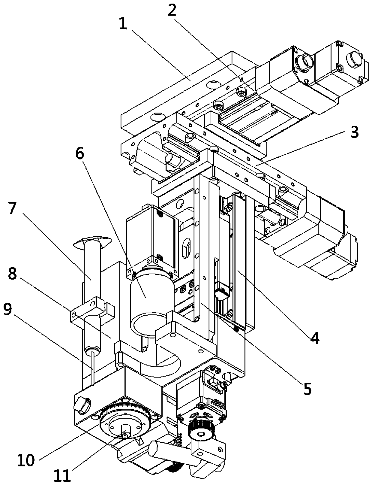
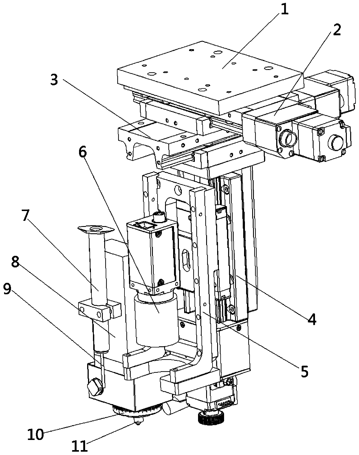
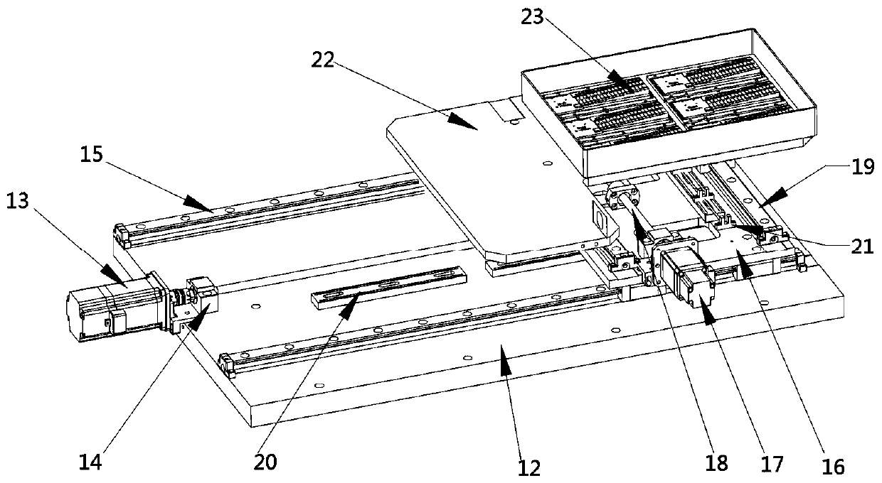
The invention relates to the field of mounting of optical devices and discloses a lens laminating system and method. The system comprises a precise location system; the precise location system comprises a spatial electric sliding table and an industrial camera component, the industrial camera component is arranged at the bottom of the spatial electric sliding table, the industrial camera componentis used for judging the exact location of a material box or base arranged below, a grabbing device is also arranged at the bottom of the spatial electric sliding table, and the material box is used for placing a lens. The lens laminating system and method which are provided by the invention have the advantages that the spatial electric sliding table is arranged, so that the grabbing device can bedriven to move in space, and the lens laminating system can automatically move to the material box and the base; the industrial camera component is arranged, so that locations of the material box andthe base can be precisely judged, and the grabbing device can effectively grab a lens and laminate the lens on the base; and the lens laminating system disclosed by the invention can automatically realize laminating of the lens, so that labor intensity is reduced and precision and efficiency are improved.

Description

technical field [0001] The invention relates to the field of optical device installation, in particular to a lens bonding system and method. Background technique [0002] In recent years, methods of bonding optical films and sheets such as polarizing plates and lens sheets (hereinafter collectively referred to as optical sheets) to bases such as glass substrates to produce various devices such as thin display panels have been developed. In semiconductor lasers, it is often necessary to attach a lens to a chip in order to achieve light concentration. Attaching the optical sheet to the base can facilitate the arrangement of the optical sheet, and this technology has been widely used. [0003] Lens fitting means fitting and setting the lens on the corresponding base, so that the arrangement of the lens can be realized by arranging the base, which can facilitate the precise arrangement of the lens. In the existing lens bonding process, manual operation is mostly used. Specifi...

Claims


Application Information

Patent Timeline
IPC IPC(8): G02B7/02G02B27/62
Inventor 郭庆锐黄思琪苏文毅
Owner WUHAN RAYCUS FIBER LASER TECHNOLOGY CO LTD
Why Eureka
Try Eureka