Eureka AIR delivers breakthrough ideas for toughest innovation challenges, trusted by R&D personnel around the world.

A broadband RFID tag printed antenna structure

A technology of RFID tag and antenna structure, applied in the field of radio frequency transmission, can solve the problems of high processing accuracy, increase product cost, and difficult to debug, and achieve the effect of ensuring reliability, reducing product production cost, and improving use effect.

Active Publication Date: 2020-07-03
南京杰思微电子技术有限公司
View PDF7 Cites 0 Cited by
  • Summary
  • Abstract
  • Description
  • Claims
  • Application Information

AI Technical Summary

Problems solved by technology

However, it is difficult for the general printed dipole antenna to achieve broadband conjugate matching with the RFID chip in a small size, so that in practical applications, the antenna needs to be repeatedly developed and debugged for different regions of use, which will increase product costs
[0005] The existing broadband RFID antenna design scheme is mainly based on the fractal form, which requires high processing accuracy on small-sized PCBs and is not easy to debug

Method used


Image

  • A broadband RFID tag printed antenna structure
  • A broadband RFID tag printed antenna structure
  • A broadband RFID tag printed antenna structure

Examples


Embodiment Construction

[0027] The specific implementation manners of the present invention will be further described in detail below in conjunction with the accompanying drawings.

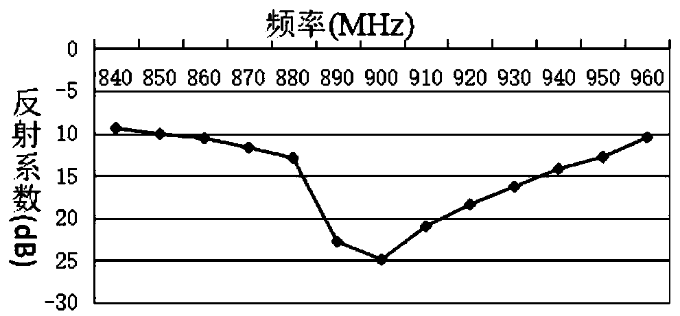
[0028] The present invention designs a broadband RFID label printed antenna structure, in practical application, such as figure 1 and figure 2 As shown, it includes a dielectric substrate 1 and a radiating structure disposed on the upper surface of the dielectric substrate 1; wherein, the radiating structure includes two radiating unit groups with the same structure, and each radiating unit group includes at least two radiating units 2, each The radiation units 2 are metal straight lines arranged on the upper surface of the dielectric substrate 1 .

[0029] In each radiating unit group, each radiating unit 2 is arranged parallel to each other on the upper surface of the dielectric substrate 1, and along a single direction perpendicular to the straight line where the radiating unit 2 is located, the length of each radia...


PUM


Abstract

The invention relates to a broadband RFID tag printed antenna structure. Better full-band matching design is provided for bands supported by an RFID chip on a smaller PCB, and specific size can be designed according to different application environment requirements, so that the RFID tag product can be better used on surfaces of metal and non-metal. In actual use, designed parameters are flexible and are convenient to debug in practice, a single layer of PCB is adopted, so that PCB processing requirements are not high, RFID chip communication quality is ensured, further, product production costis lowered, and design reliability is ensured.

Description

technical field [0001] The invention relates to a broadband RFID label printed antenna structure, which belongs to the technical field of radio frequency transmission. Background technique [0002] In order to ensure that the cost of UHF RFID tag products can be controlled and the products can meet the reliability design requirements, the antenna is often directly connected to the RFID chip, so the impedance matching of the input port of the RFID chip is completely borne by the antenna. For passive RFID chip design, its input impedance changes with frequency, so it brings challenges to broadband antenna design. [0003] Since the implementation of communication coding, error correction and modulation methods in the passive RFID underlying protocol is relatively simple, the quality of wireless communication cannot be guaranteed. Therefore, passive RFID chips are mostly in the form of differential input and output, so as to increase the transmission rate and eliminate environm...

Claims


Application Information

Patent Timeline
Patent Type & Authority Patents(China)
IPC IPC(8): H01Q1/38H01Q9/28H01Q1/22G06K19/077
Inventor 喻洋章梁晴汤颢达民权金忠李畅张培
Owner 南京杰思微电子技术有限公司
Why Eureka
Eureka Blog
Learn More