
Series hybrid permanent-magnet adjustable magnetic flux motor with reverse salient pole characteristic

A saliency characteristic and hybrid permanent magnet technology, which is applied in the direction of magnetic circuit rotating parts, magnetic circuit shape/style/structure, etc., can solve the problems of difficulty in adjusting the magnetization level of permanent magnets, high power density, and small magnetization current. Achieve the effect of small magnetizing current, high power density, and prevent demagnetization

Inactive Publication Date: 2019-05-10
HARBIN INST OF TECH
View PDF6 Cites 3 Cited by
  • Summary
  • Abstract
  • Description
  • Claims
  • Application Information

AI Technical Summary

Problems solved by technology

[0003] The series-type hybrid permanent magnet adjustable flux motor with anti-saliency characteristics proposed by the present invention has a smaller magnetization current than the series-type adjustable flux motor without quadrature-axis magnetic barriers, and solves the problem of series-type adjustable flux motors. Flux motors have the problem of difficulty in adjusting the magnetization level of low coercivity permanent magnets; and compared with parallel adjustable flux motors, they have higher power density and are suitable for a variety of places with higher power density

Method used


Image

  • Series hybrid permanent-magnet adjustable magnetic flux motor with reverse salient pole characteristic
  • Series hybrid permanent-magnet adjustable magnetic flux motor with reverse salient pole characteristic
  • Series hybrid permanent-magnet adjustable magnetic flux motor with reverse salient pole characteristic

Examples


specific Embodiment approach 1

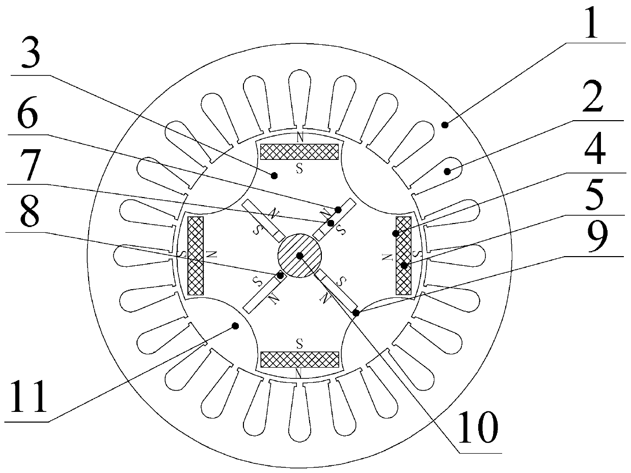
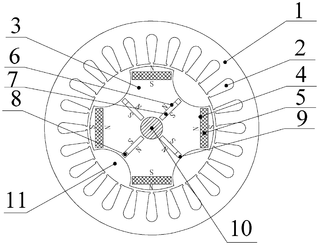
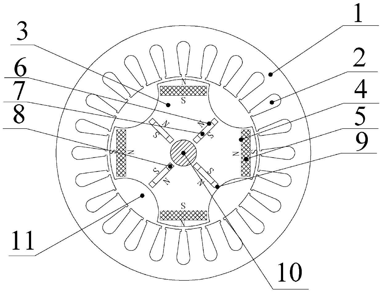
[0025] Specific implementation mode one: the following combination Figure 1-5 To illustrate this embodiment, the series-type hybrid permanent magnet adjustable flux motor with anti-saliency characteristics described in the present invention includes a stator core 1, an armature winding 2, a rotor core 3 and a rotating shaft 10; the rotor core 3 is fixed on the rotating shaft 10 and located inside the stator core 1, the armature winding 2 is set on the stator core 1;

[0026] It also includes a low-coercivity permanent magnet slot 4, a low-coercivity permanent magnet 5, a high-coercivity permanent magnet slot 6, a high-coercivity permanent magnet 7, a magnetic isolation slot 8 and a cross-axis magnetic barrier 11;

[0027] A plurality of quadrature-axis magnetic barriers 11 are evenly distributed along the outer circular surface of the rotor core 3, and the quadrature-axis magnetic barriers 11 are indented at the junction of the quadrature axis under each magnetic pole and the...

specific Embodiment approach 2

[0031] Embodiment 2: The difference between this embodiment and Embodiment 1 is that the concave boundary line of the radial section of the quadrature-axis magnetic barrier 11 is a circular arc, figure 1 The shown embodiment 1, figure 2 Shown in Example 2, image 3 The illustrated embodiment 3 uses circular arcs.

[0032] Or the concave boundary line of the radial section of the cross-axis magnetic barrier 11 is a straight line segment+arc+straight line segment, and the straight line segments at both ends of the boundary line correspond to the short sides of the low coercive force permanent magnet slot 4, and the low coercive force permanent magnet slot 4 The straight line section of the short side quadrature axis magnetic barrier 11 may be greater than or equal to or smaller than the short side of the low coercivity permanent magnet slot 4 . Figure 4 The shown embodiment 4 adopts straight line segment+arc+straight line segment.

[0033] Or the concave boundary line of th...

specific Embodiment approach 3

[0035]Specific embodiment three: the difference between this embodiment and embodiment one or two is that the magnetization direction of the low-coercivity permanent magnet 5 is perpendicular to the long side of the radial section of the low-coercivity permanent magnet groove 4 (i.e. parallel Magnetization, the magnetization direction of the midpoint position is radial magnetization), and the magnetization direction of two adjacent low-coercivity permanent magnets 5 is opposite; the magnetization direction of the high-coercivity permanent magnet 7 is perpendicular to the high The long sides of the coercive force permanent magnet slot 6 radial sections are parallel magnetization, and the direction is tangential magnetization, and the magnetization directions of two adjacent high coercive force permanent magnets 7 are opposite. Under the same magnetic pole, the low The coercive force permanent magnet 5 and the high coercive force permanent magnet 7 are both N poles or S poles.


PUM


Abstract

The invention relates to a series hybrid permanent-magnet adjustable magnetic flux motor with reverse salient pole characteristic, and belongs to the field of permanent-magnet motors. By the series hybrid permanent-magnet adjustable magnetic flux motor with reverse salient pole characteristic, the problems that the magnetization level of a low-coercivity permanent magnet is difficult to adjust ina series adjustable magnetic flux motor is solved. The series hybrid permanent-magnet adjustable magnetic flux motor with reverse salient pole characteristic is characterized in that a plurality of quadrature-axis magnetic obstacles are uniformly arranged along a surface of an outer circle of a rotor core, each quadrature-axis magnetic obstacle is sunken and formed at a junction of the quadratureaxis under each magnetic pole and the surface of the outer circle of the rotor core, a tangential low-coercivity permanent magnet is arranged at a position, near to a pole top, in a rotor pole formedbetween each two adjacent sunken regions, a radial high-coercivity permanent body is arranged at a position, corresponding to the sunken region, of the rotor core, the low-coercivity permanent magnetis arranged in a low-coercivity permanent magnet groove, the high-coercivity permanent magnet is arranged in a high-coercivity permanent magnet groove, and the low-coercivity permanent magnet groove and the high-coercivity permanent magnet groove penetrate through the whole motor along an axial direction.

Description

technical field [0001] The invention relates to a series type hybrid permanent magnet adjustable flux motor rotor structure with anti-saliency characteristics, belonging to the field of permanent magnet motors. Background technique [0002] Traditional permanent magnet synchronous motors are widely used in aerospace, industrial control, transportation and household appliances due to their high power factor and high power density. However, since the magnetization state of the high-coercivity permanent magnets such as neodymium-iron-boron is difficult to adjust, the motor needs to use a weak magnetic method to reduce the no-load back electromotive force proportional to the motor rotation speed when the motor is running at high speed. Field weakening currents cause additional copper loss which reduces motor efficiency. In order to solve this problem, an adjustable flux motor, which can use the armature winding pulse current to adjust the magnetization state of the low coercivi...

Claims


Application Information

Patent Timeline
Patent Type & Authority Applications(China)
IPC IPC(8): H02K1/27H02K1/24
Inventor 郑萍刘法亮王明峤刘国鹏马栋宇吴冬亮尤莹
Owner HARBIN INST OF TECH
Learn More