Built-in double-V-shaped series-parallel hybrid magnetic circuit adjustable magnetic flux permanent magnet synchronous motor

A permanent magnet synchronous motor and hybrid magnetic circuit technology, applied in synchronous motors with static armatures and rotating magnets, synchronous machine parts, magnetic circuit rotating parts, etc., to achieve small demagnetization current, increase power density, The effect of small magnetizing current

Inactive Publication Date: 2019-05-31
HARBIN INST OF TECH
View PDF5 Cites 19 Cited by
  • Summary
  • Abstract
  • Description
  • Claims
  • Application Information

AI Technical Summary

Problems solved by technology

[0003] The purpose of the present invention is to solve the problems existing in the magnetic adjustment process of the existing permanent magnet motor, and to provide a built-in double V-type series-parallel hybrid magnetic circuit adjustable flux permanent magnet synchronous motor

Method used


Image

  • Built-in double-V-shaped series-parallel hybrid magnetic circuit adjustable magnetic flux permanent magnet synchronous motor
  • Built-in double-V-shaped series-parallel hybrid magnetic circuit adjustable magnetic flux permanent magnet synchronous motor
  • Built-in double-V-shaped series-parallel hybrid magnetic circuit adjustable magnetic flux permanent magnet synchronous motor

Examples


Embodiment 1

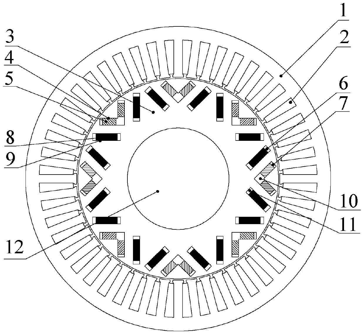
[0026] Embodiment 1: see figure 1 , the motor includes a stator core 1, an armature winding 2, a rotor core 3, a rotating shaft 12, a low-coercivity permanent magnet 5, a high-coercivity permanent magnet 8, an inner V-tip magnetic isolation groove 10, and an inner V air gap side Magnetic isolation slot 7, magnetic isolation slot 6 on the outer V air gap side, and magnetic isolation slot 11 on the outer V shaft side; the rotor core 3 is fixed on the rotating shaft 12, the armature winding 2 is located in the stator core 1, the stator core 1 and the rotor core 3 There is a radial air gap between them;

[0027] The air-gap side body of the rotor core 3 has multiple permanent magnets built in to form a P pair of magnetic poles. Each pole includes two low-coercivity permanent magnets 5 and two high-coercivity permanent magnets 8, and two low-coercivity permanent magnets. 5 Take the pole rotor direct axis as the symmetry line to form a V shape symmetrically, and the V-shaped tip is...

Embodiment 2

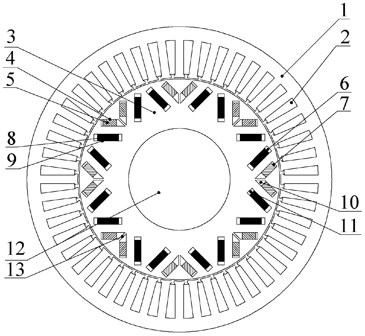
[0033] Example 2: see figure 2 , is improved on the basis of Embodiment 1, and further includes a central rib 13, which is arranged inside the inner V-tip magnetic isolation groove 10 along the direction of the rotor direct axis, and divides the trapezoidal groove into two parts.

[0034]The purpose of providing the central rib 13 in this embodiment is to improve the mechanical strength of the rotor. The width of the central rib 13 can be reasonably selected after comprehensively considering the mechanical strength and electromagnetic performance requirements of the motor.

Embodiment 3

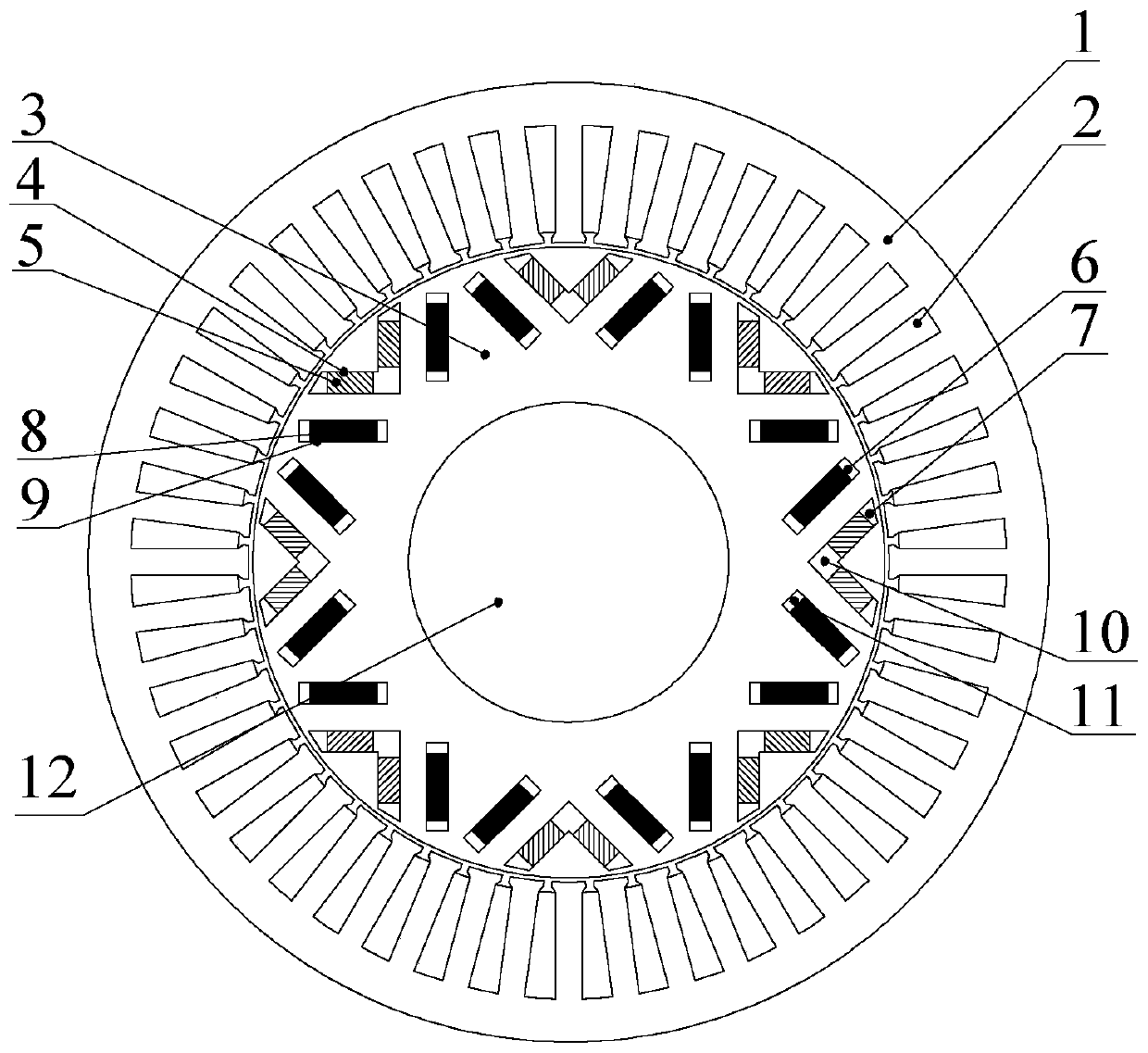
[0035] Embodiment 3: see image 3 , improved on the basis of Example 1, the inner V-tip magnetic isolation groove 10 is a trapezoidal groove, and two low-coercivity permanent magnets 5 are connected at the same time, located at the V-shaped tip formed by two low-coercivity permanent magnets 5 ; The magnetic isolation slot 6 on the outer V air gap side and the magnetic isolation slot 11 on the outer V shaft side are both rectangular slots. The magnetic isolation groove 7 on the inner V air gap side is replaced by a trapezoidal groove.

[0036] In this embodiment, the purpose of setting trapezoidal magnetic isolation grooves on the rotor air gap side is to form a magnetic bridge, limit the magnetic flux passing through the magnetic bridge, and not only reduce the magnetic flux leakage generated by the low-coercivity permanent magnet 5 due to its own short circuit, but also Reduced the influence that high-coercivity permanent magnet 8 produces on low-coercivity permanent magnet ...


PUM


Abstract

The built-in double-V-shaped series-parallel hybrid magnetic circuit adjustable magnetic flux permanent magnet synchronous motor belongs to the field of permanent magnet motors and solves the complexstructure and the high cost of a conventional device for generating radial polarized light and angular polarized light. A plurality of permanent magnets are built in a rotor core air gap side body toform P pairs of magnetic poles. Each magnetic pole comprises two low-coercive-force permanent magnets and two high-coercive-force permanent magnets. The two low-coercive-force permanent magnets are arranged symmetric about the rotor straight axis of the magnetic pole to form a V shape. An inner V-tip magnetic isolation groove is connected with the two low-coercive-force permanent magnets simultaneously. The two high-coercive-force permanent magnets are arranged symmetric about the rotor straight axis of the magnetic pole to form a V shape and are located outside the two low-coercive-force permanent magnets. The low-coercive-force permanent magnet and the high-coercive-force permanent magnets on the same side of the rotor straight axis are arranged in parallel. The V-shaped tips of the twohigh-coercive-force permanent magnets do not communicate with each other.

Description

technical field [0001] The invention relates to a built-in double V-type series-parallel hybrid magnetic circuit adjustable magnetic flux permanent magnet synchronous motor rotor structure, which belongs to the field of permanent magnet motors. Background technique [0002] Traditional rare earth permanent magnet synchronous motors have the advantages of high power factor, high power density, high efficiency, and high reliability, and are widely used in electric vehicles, rail transit, household appliances, aerospace and defense industries and other fields. Traditional high-performance rare-earth permanent-magnet synchronous motors generally use high-coercivity permanent magnets such as NdFeB. The air-gap magnetic field of the motor is difficult to adjust, resulting in a narrow constant power area and a narrow speed regulation range when the motor is running electrically. In order to obtain a wide range of speed regulation and to realize constant power control when the perma...

Claims


Application Information

Patent Timeline
Patent Type & Authority Applications(China)
IPC IPC(8): H02K21/14H02K21/02H02K1/27
Inventor 刘勇乔光远程路明刘法亮苑子航郑萍
Owner HARBIN INST OF TECH
Why Eureka
Try Eureka