Built-in V-type-U-type serial-parallel hybrid magnetic circuit adjustable magnetic flux permanent magnet synchronous motor
A technology of permanent magnet synchronous motor and hybrid magnetic circuit, which is applied in the direction of synchronous motor with stationary armature and rotating magnet, magnetic circuit, magnetic circuit rotating parts, etc., to achieve small magnetizing current, wide speed regulation range, and easy The effect of charge and demagnetization
- Summary
- Abstract
- Description
- Claims
- Application Information
AI Technical Summary
Problems solved by technology
Method used
Image
Examples
Embodiment 1
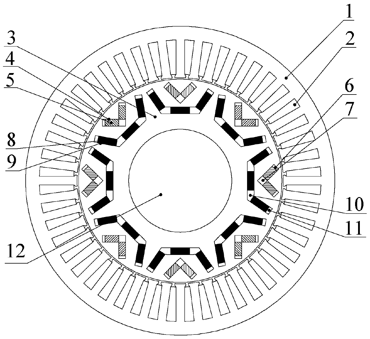
[0024] Embodiment 1: see figure 1 The motor of the present invention includes a stator core 1, an armature winding 2, a rotor core 3, a rotating shaft 12, a low-coercivity permanent magnet 5, a high-coercivity permanent magnet 8, a V-shaped end magnetic separation slot 6, a V-shaped tip spacer Magnetic slot 7, U-shaped bottom angle magnetic isolation slot 10 and U-shaped end magnetic isolation slot 11; the rotor core 3 is fixed on the rotating shaft 12, the armature winding 2 is located in the stator core 1, between the stator core 1 and the rotor core 3 There is a radial air gap;
[0025] Rotor core 3 has multiple permanent magnets built into the body on the air gap side to form a P pair of magnetic poles. Each magnetic pole includes two low-coercivity permanent magnets 5 and three high-coercivity permanent magnets 8. Three high-coercivity permanent magnets 8. A U-shaped structure is arranged symmetrically with the direct axis of the magnetic pole rotor as a line of symmetry...
Embodiment 2
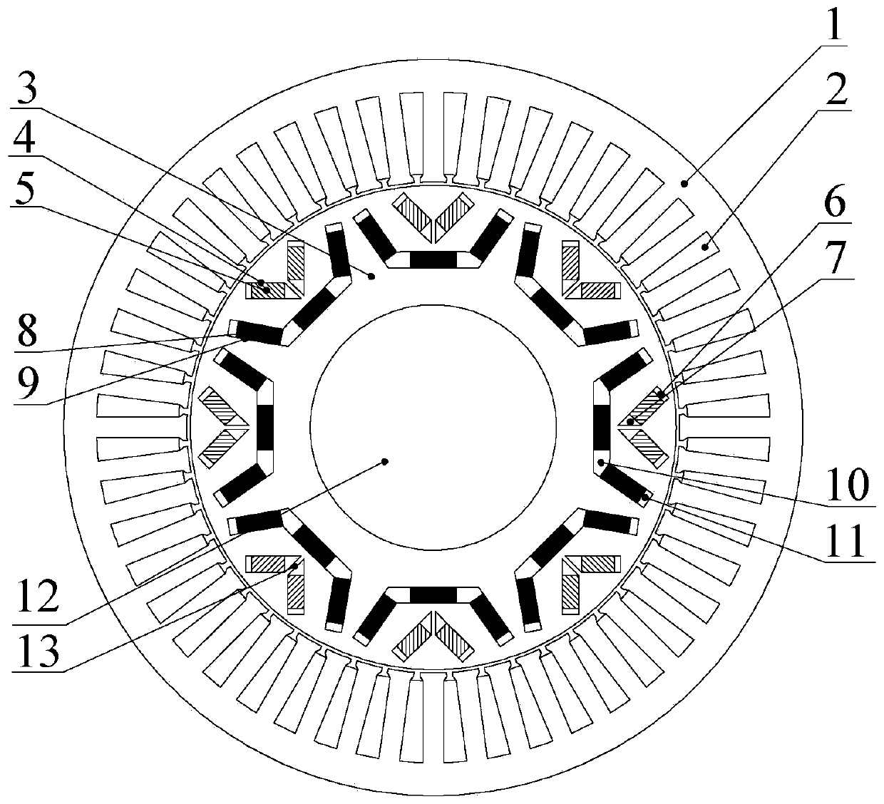
[0033] Example 2: see figure 2 , is improved on the basis of Embodiment 1, and also includes a central rib 13, which is arranged inside the V-shaped tip magnetic isolation groove 7 along the direction of the rotor direct axis, and divides the groove into two parts.
[0034] The purpose of this embodiment is to improve the mechanical strength of the rotor. The width of the central rib 13 can be reasonably selected after comprehensively considering the mechanical strength and electromagnetic performance requirements of the motor.
Embodiment 3
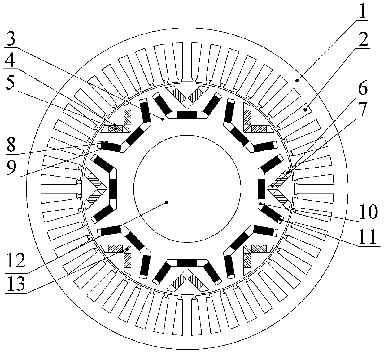
[0035] Embodiment 3: see image 3 , improve on the basis of Example 2, the V-shaped end magnetic separation groove 6 is replaced by a trapezoidal groove, the purpose of this setting is to form a magnetic bridge on the rotor air gap side, limit the magnetic flux passing through the magnetic bridge, not only reduce the low The coercive force permanent magnet 5 is caused by self-short circuit leakage, and reduces the impact of the high coercive force permanent magnet 8 on the low coercive force permanent magnet 5, and increases the effect on the low coercive force permanent magnet 5 simultaneously. The direct-axis component of the armature charge and demagnetization magnetic potential makes it easier to realize charge and demagnetization, and the speed regulation range of the motor is wider.
PUM
 Abstract
Description
Claims
Application Information
 - R&D
- Intellectual Property
- Life Sciences
- Materials
- Tech Scout
- Unparalleled Data Quality
- Higher Quality Content
- 60% Fewer Hallucinations
Browse by: Latest US Patents, China's latest patents, Technical Efficacy Thesaurus, Application Domain, Technology Topic, Popular Technical Reports.
© 2025 PatSnap. All rights reserved.Legal|Privacy policy|Modern Slavery Act Transparency Statement|Sitemap|About US| Contact US: help@patsnap.com


