Built-in line-shaped/U-shaped series-parallel hybrid magnetic circuit adjustable magnetic flux permanent magnet synchronous motor

A permanent magnet synchronous motor and hybrid magnetic circuit technology, which is applied to synchronous motors with stationary armatures and rotating magnets, synchronous machine parts, magnetic circuit rotating parts, etc., to achieve reduced magnetic flux leakage, small demagnetization current, Effect of increased power density

Inactive Publication Date: 2019-05-31
HARBIN INST OF TECH
View PDF7 Cites 6 Cited by
  • Summary
  • Abstract
  • Description
  • Claims
  • Application Information

AI Technical Summary

Problems solved by technology

[0003] The purpose of the present invention is to solve the problems existing in the magnetic adjustment process of the existing permanent magnet motor, and to provide a built-in inline-U-shaped series-parallel hybrid magnetic circuit adjustable flux permanent magnet synchronous motor

Method used


Image

  • Built-in line-shaped/U-shaped series-parallel hybrid magnetic circuit adjustable magnetic flux permanent magnet synchronous motor
  • Built-in line-shaped/U-shaped series-parallel hybrid magnetic circuit adjustable magnetic flux permanent magnet synchronous motor

Examples


Embodiment 1

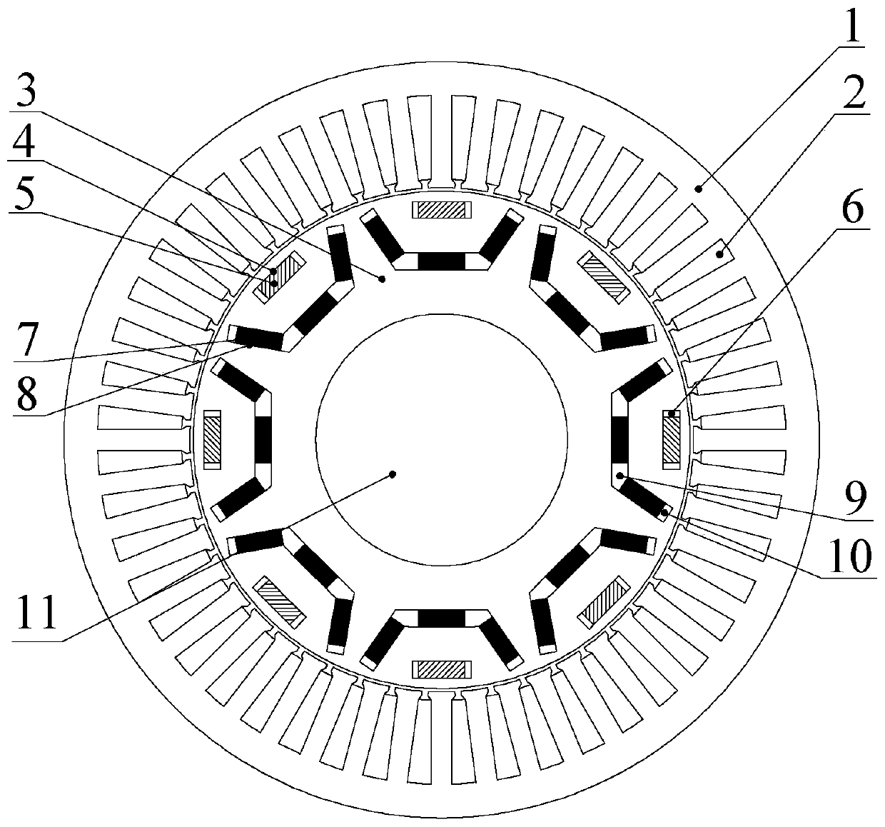
[0021] Embodiment 1: see figure 1 The motor of the present invention includes a stator core 1, an armature winding 2, a rotor core 3, a rotating shaft 11, a low-coercivity permanent magnet 5, a high-coercivity permanent magnet 7, a first magnetic isolation slot 6, and a second magnetic isolation slot 9 and the third magnetic isolation slot 10; the rotor core 3 is fixed on the rotating shaft 11, the armature winding 2 is located in the stator core 1, and there is a radial air gap between the stator core 1 and the rotor core 3;

[0022] The rotor core 3 has multiple permanent magnets built into the body on the air gap side to form a P pair of magnetic poles. Each magnetic pole includes a low-coercivity permanent magnet 5 and three high-coercivity permanent magnets 7, and three high-coercivity permanent magnets 7 Set up a U-shaped structure symmetrically with the direct axis of the magnetic pole rotor as the line of symmetry, and the opening faces the radial air gap. A low-coerci...

Embodiment 2

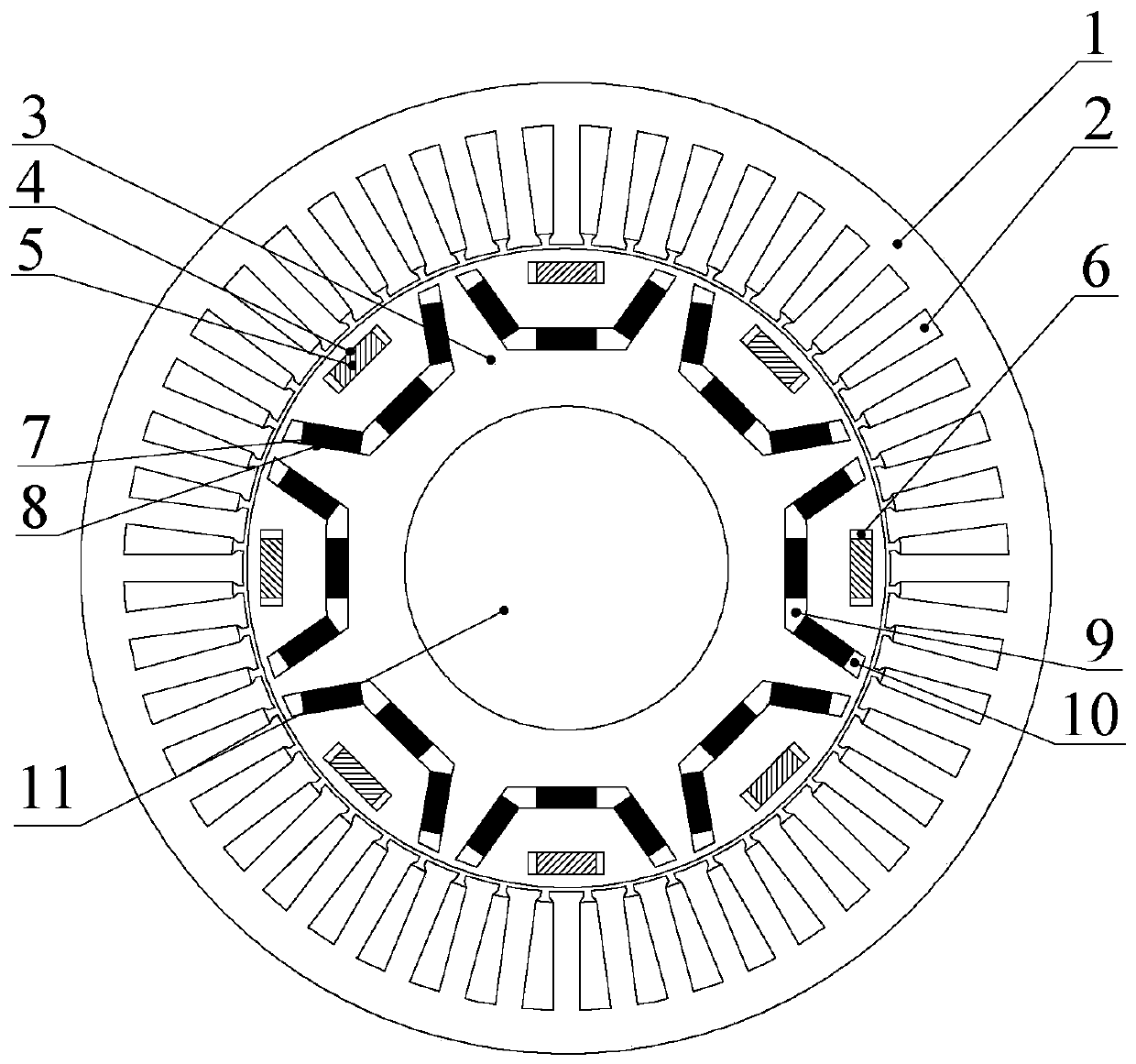
[0029] Example 2: see figure 2 , Improvement is made on the basis of Embodiment 1, the radial section of the third magnetic isolation slot 10 is trapezoidal.

[0030] The purpose of this embodiment is to form a magnetic bridge on the air gap side of the rotor to limit the magnetic flux passing through the magnetic bridge, which can not only reduce the magnetic flux leakage of the high coercivity permanent magnet 7 caused by its own short circuit, but also reduce the adjacent The flux leakage between the high-coercivity permanent magnets 7 between the two magnetic poles improves the air-gap magnetic density, and the power density of the motor increases.


PUM


Abstract

The built-in line-shaped/U-shaped series-parallel hybrid magnetic circuit adjustable magnetic flux permanent magnet synchronous motor belongs to the field of permanent magnet motors and solves the problems in the magnetic modulating process of the existing permanent magnet motor. A plurality of permanent magnets are built in the air gap side body of a rotor core 3 to constitute P pairs of magneticpoles. Each magnetic pole comprises a low-coercive-force permanent magnet 5 and three high-coercive-force permanent magnets 7. The three high-coercive-force permanent magnets 7 are arranged symmetricabout the rotor straight axis of the magnetic pole to form a U-shaped structure and opening of the U-shaped structure faces a radial air gap. The low-coercive-force permanent magnet 5 is disposed atthe opening of the U-shaped structure. The low-coercive-force permanent magnet 5 is arranged tangentially with the rotor straight axis of the magnetic pole as a symmetrical line to form a line-shapedstructure. First magnetic isolation grooves 6 are disposed at both ends of the low-coercive-force permanent magnet 5. Both end portions of the opening of the U-shaped structure are provided with a third magnetic isolation groove 10. The two bottom corners of the U-shaped structure are each provided with a second magnetic isolation groove 9.

Description

technical field [0001] The invention relates to a built-in inline-U-shaped series-parallel hybrid magnetic circuit adjustable flux permanent magnet synchronous motor rotor structure, which belongs to the field of permanent magnet motors. Background technique [0002] Traditional rare earth permanent magnet synchronous motors have the advantages of high power factor, high power density, high efficiency, and high reliability, and are widely used in electric vehicles, rail transit, household appliances, aerospace and defense industries and other fields. Traditional high-performance rare-earth permanent-magnet synchronous motors generally use high-coercivity permanent magnets such as NdFeB. The air-gap magnetic field of the motor is difficult to adjust, resulting in a narrow constant power area and a narrow speed regulation range when the motor is running electrically. In order to obtain a wide range of speed regulation and to realize constant power control when the permanent ma...

Claims


Application Information

Patent Timeline
Patent Type & Authority Applications(China)
IPC IPC(8): H02K21/14H02K21/02H02K1/27
Inventor 佟诚德王明峤乔光远刘国鹏尹佐生郑萍
Owner HARBIN INST OF TECH
Why Eureka
Try Eureka