Electrocardiosignal waveform detection method

A technology for ECG signal and waveform detection, which is applied in the field of ECG signal waveform detection, identification and detection of P waves in ECG signal waveforms, and can solve the problem of P wave positioning deviation, large positioning deviation of the starting point and end point of P wave, and failure to achieve good results. problems such as the effect of reducing positioning deviation and improving recognition accuracy

Active Publication Date: 2019-05-14
SHENZHEN UNIV
View PDF5 Cites 9 Cited by
  • Summary
  • Abstract
  • Description
  • Claims
  • Application Information

AI Technical Summary

Problems solved by technology

The detection of P waves by the low-pass differential method usually relies on a single threshold setting. Since the P waves of ECG waveforms obtained from different leads or at different times are quite different and are easily affected by noise, a single threshold can easily cause P-wave positioning errors. deviation
Although the wavelet transform method has improved the ability to remove noise, because the P and T waves are on the same scale, this method cannot achieve good results for how to distinguish T waves, PT wave fusion, and severe noise interference.
[0005] In the prior art, due to the low-amplitude and low-frequency characteristics of the P wave, it is very susceptible to noise interference, and there are PT wave fusion, u-wave interference, and some lead P waves are not obvious, and the starting position of the P wave is difficult to accurately locate. , usually the deviations in the positioning of the start and end of the P wave are relatively large

Method used


Image

  • Electrocardiosignal waveform detection method
  • Electrocardiosignal waveform detection method
  • Electrocardiosignal waveform detection method

Examples


Embodiment Construction

[0034] Embodiments of the present invention will be described in further detail below in conjunction with the accompanying drawings.

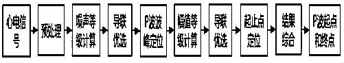
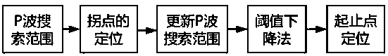
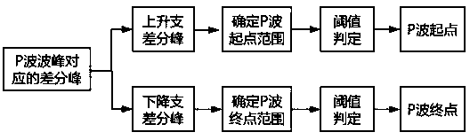
[0035] Such as Figures 1 to 3 In the illustrated embodiment of the method for detecting the waveform of an electrocardiographic signal, a plurality of steps including steps A to G are included. In step A, preprocess the ECG signal waveforms of N leads; filter out the myoelectric noise in the ECG signal waveforms of each lead, filter out power frequency interference and baseline drift; Filter to filter EMG signals; set a low-pass filter with a cutoff frequency of 48Hz and a high-pass filter with a cutoff frequency of 52Hz to remove 50Hz power frequency interference signals; set a high-pass filter with a cutoff frequency of 1Hz to suppress baseline drift; The preprocessed ECG signal waveforms of N leads are used for subsequent feature point detection; wherein N is a natural number greater than or equal to 6; in the first embodiment, N is 18. e...


PUM


Abstract

The invention discloses an electrocardiosignal waveform detection method. The method comprises the steps that step B, position information of starting points and end points of QRS waves of N lead electrocardiosignal waveforms and position information of end points of T waves of the N lead electrocardiosignal waveforms are acquired; step C, the N lead electrocardiosignal waveforms are subjected tosignal quality grade ranking; step D, first six preferred leads with the minimum signal quality SQ values are selected for P wave detection; step E, P wave crest amplitude values of the six preferredleads are ranked; step F, electrocardiosignal waveforms of the first four preferred leads in the P wave crest amplitude value grade AL in the step E are selected for location of starting points and end points of P waves; step G, according to the acquired positions of the starting points and end points of the P waves of the electrocardiosignal waveforms of the four preferred leads, the positions ofthe starting points and end points of the P waves are comprehensively analyzed, and position information of the starting points and end points of the P waves is output. Through multi-level screening,a lead group of the optimum signal quality and the higher P wave crest value is found and is subjected to feature point detection, and the detection accuracy is improved.

Description

technical field [0001] The invention relates to the field of signal detection and analysis, in particular to an electrocardiographic signal waveform detection method, in particular to the identification and detection of P waves in the electrocardiographic signal waveform. Background technique [0002] Using an electrocardiogram machine to record the electrocardiogram corresponding to the heart activity of each cardiac cycle of the patient from the body surface is one of the most commonly used technical means for clinical arrhythmia analysis. [0003] Typical ECG signal waveforms include the QRS wave representing the ventricular depolarization process, and the P wave representing the atrial depolarization process. In ECG analysis, parameters such as the duration, amplitude, shape, PR interval, and P wave axis of P wave are important criteria for arrhythmia analysis. For example, the presence or absence of P waves is one of the main bases for judging premature ventricular con...

Claims


Application Information

Patent Timeline
Patent Type & Authority Applications(China)
IPC IPC(8): A61B5/0402A61B5/0452
Inventor 叶继伦陈苹王凡
Owner SHENZHEN UNIV
Why Eureka
Try Eureka