Bottom dead center absolute value detection device and method

A detection device and absolute value technology, applied in presses, metal processing equipment, metal processing, etc., can solve the problems of low bottom dead center positioning accuracy, lack of compensation ability, and cumbersome adjustment process.

Active Publication Date: 2020-08-11
东莞市申皓精密机械设备有限公司
View PDF8 Cites 0 Cited by
  • Summary
  • Abstract
  • Description
  • Claims
  • Application Information

AI Technical Summary

Problems solved by technology

[0002] The bottom dead point of the punch press is the position when the die plate on the punch press runs to the lowest point. When the upper die plate runs vertically downward to the bottom dead point position, whether the lower end surface of the upper die plate and the upper end face of the lower die plate are in a relatively parallel state is the stamping The key to producing precision parts. With the development of production technology, precision stamping has higher and higher requirements for the bottom dead point position of the upper platen. We need to detect the absolute value of the bottom dead point (that is, the lower end of the upper platen may not reach the set The set standard position may also exceed the set standard position. The absolute value of the bottom dead point is the distance between the lower end of the upper template and the standard position). It is determined that the defect is that the adjustment process is cumbersome, and the positioning accuracy of the bottom dead point is low, and the ability to compensate is lacking. It is difficult to achieve high-precision cooperation between the upper template and the lower template, resulting in the inability to meet the stamping requirements of high-precision parts.

Method used


Image

  • Bottom dead center absolute value detection device and method
  • Bottom dead center absolute value detection device and method
  • Bottom dead center absolute value detection device and method

Examples


Embodiment Construction

[0031] The present invention will be further described below in conjunction with accompanying drawing:

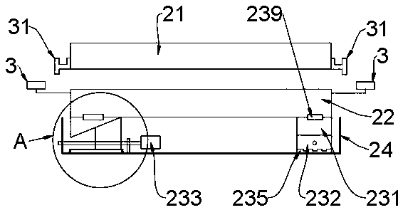
[0032] Bottom dead center absolute value detection device, including a detector, a fixing seat and four magnetic sensors 3;

[0033] Such as Figure 5 and Figure 6 The shown detector includes a PLC 11, a power module 12, a receiving module 13, a sensor module 14, a display 15, an information transmission module 16, a hard disk 17 and a filter 18, the power module 12 is electrically connected to the receiving module 13, the PLC 11, the sensor The module 14, the display 15 and the information transmission module 16 are respectively electrically connected to the receiving module 13, the sensor module 14, the information transmission module 16, the display 15 and the hard disk 17 are respectively electrically connected to the PLC 11, and the magnetic sensor 3 is electrically connected to the sensor module 14. Connect; the information transmission module 16 is provided with a...


PUM


Abstract

The invention discloses a lower dead point absolute value detection device and method. The lower dead point absolute value detection device comprises a detection instrument, a fixed seat and four magnetic sensors, wherein the detection instrument comprises a PLC, a power source module, an undertake module, a sensor module, a displayer, an information transmission module and a hard disk, the powersource module is in electrical connection with the undertake module, and the PLC, the sensor module, the displayer and the information transmission module are in electrical connection with the undertake module correspondingly; the fixed seat comprises an upper mold plate, a lower mold plate, a lower mold seat and four sets of adjustment components, the lower mold plate is arranged above the lowermold seat, and the four sets of adjustment components are arranged between the lower mold seat and the lower mold plate according to the hour pointer order; and the four magnetic sensors are arrangedat the side edges of the lower mold plate correspondingly. The lower dead point absolute value detection device and method have the advantages that the adjusting heights of the adjustment components are correspondingly and accurately calculated and controlled according to the punching machine lower dead point position, and then automatic fine adjustment of the height of the lower mold plate is realized, so that micro compensation performed on the punching machine lower dead point position is indirectly realized.

Description

technical field [0001] The invention relates to the technical field of punching machines, in particular to a bottom dead center absolute value detection device and method. Background technique [0002] The bottom dead point of the punch press is the position when the die plate on the punch press runs to the lowest point. When the upper die plate runs vertically downward to the bottom dead point position, whether the lower end surface of the upper die plate and the upper end face of the lower die plate are in a relatively parallel state, is the stamping The key to producing precision parts. With the development of production technology, precision stamping has higher and higher requirements for the bottom dead point position of the upper template. We need to detect the absolute value of the bottom dead point (that is, the lower end surface of the upper template may not have reached the design The set standard position may also exceed the set standard position. The absolute val...

Claims


Application Information

Patent Timeline
Patent Type & Authority Patents(China)
IPC IPC(8): B21C51/00B30B15/00
Inventor 陈劲君
Owner 东莞市申皓精密机械设备有限公司
Why Eureka
Try Eureka