
Assembling equipment for shaft core and shaft sleeve of potentiometer or encoder

A technology for assembly equipment and potentiometers, which is applied in assembly machines, metal processing equipment, manufacturing tools, etc. It can solve the problems of unassembled collars, low yield and assembly efficiency, and limited assembly time, etc.

Pending Publication Date: 2019-05-14
广东钺河智能科技有限公司
View PDF0 Cites 5 Cited by
  • Summary
  • Abstract
  • Description
  • Claims
  • Application Information

AI Technical Summary

Problems solved by technology

[0002] The potentiometer (English: Potentiometer) is a kind of variable resistor, usually composed of a resistor body and a rotating or sliding system, that is, a movable contact moves on the resistor body to obtain part of the voltage output. The function of the potentiometer is Adjust the magnitude of voltage (including DC voltage and signal voltage) and current; an encoder (encoder) is a device that compiles and converts signals (such as bit streams) or data into signal forms that can be used for communication, transmission, and storage. Encoders Convert angular displacement or linear displacement into electrical signals; Among them, in the structure of the potentiometer or encoder, the shaft core and sleeve are important components. In the traditional production process, the shaft core and sleeve are generally assembled manually. At the same time, it is necessary to manually set the sleeve on the shaft core, and use tools to clamp the collar on the shaft core to avoid the separation of the shaft sleeve and the shaft core. In this way, workers need to work hard to set the collar On the shaft core, it is also prone to the situation that the collar is not assembled in place, so that the assembly time is severely limited, and the yield rate and assembly efficiency are low

Method used


Image

  • Assembling equipment for shaft core and shaft sleeve of potentiometer or encoder
  • Assembling equipment for shaft core and shaft sleeve of potentiometer or encoder
  • Assembling equipment for shaft core and shaft sleeve of potentiometer or encoder

Examples


Embodiment Construction

[0046] The present invention will be further described below in conjunction with accompanying drawing of description:

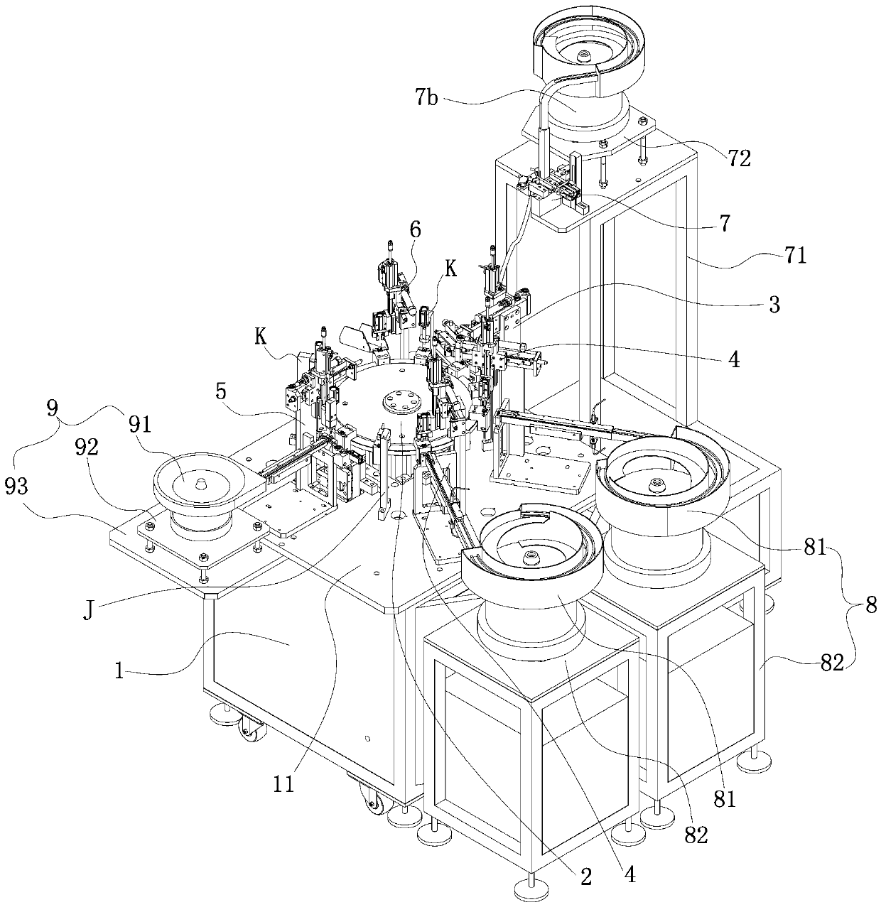
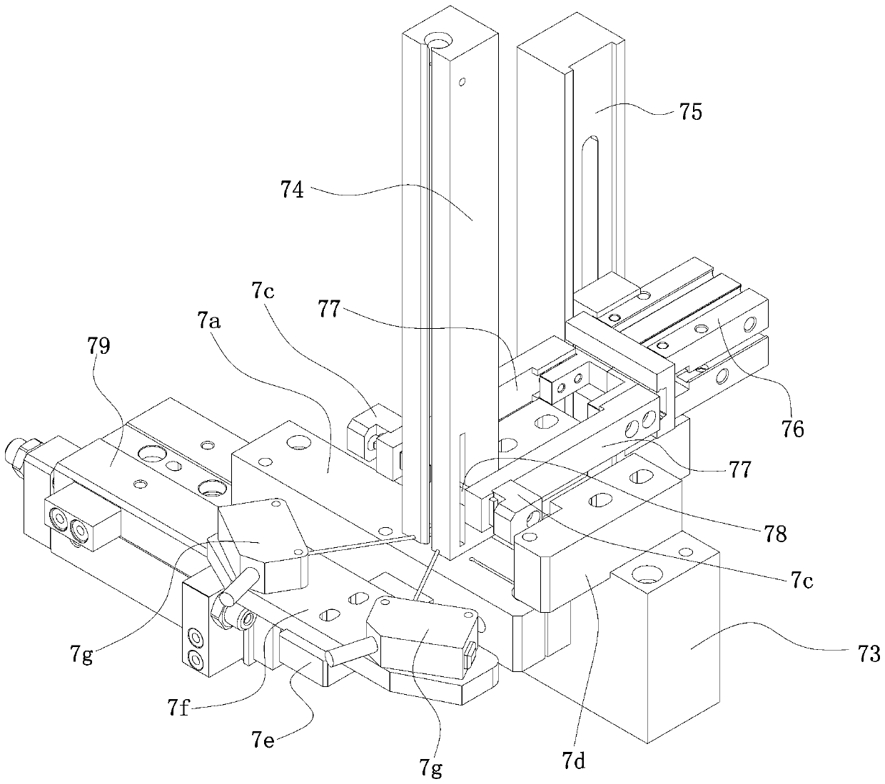
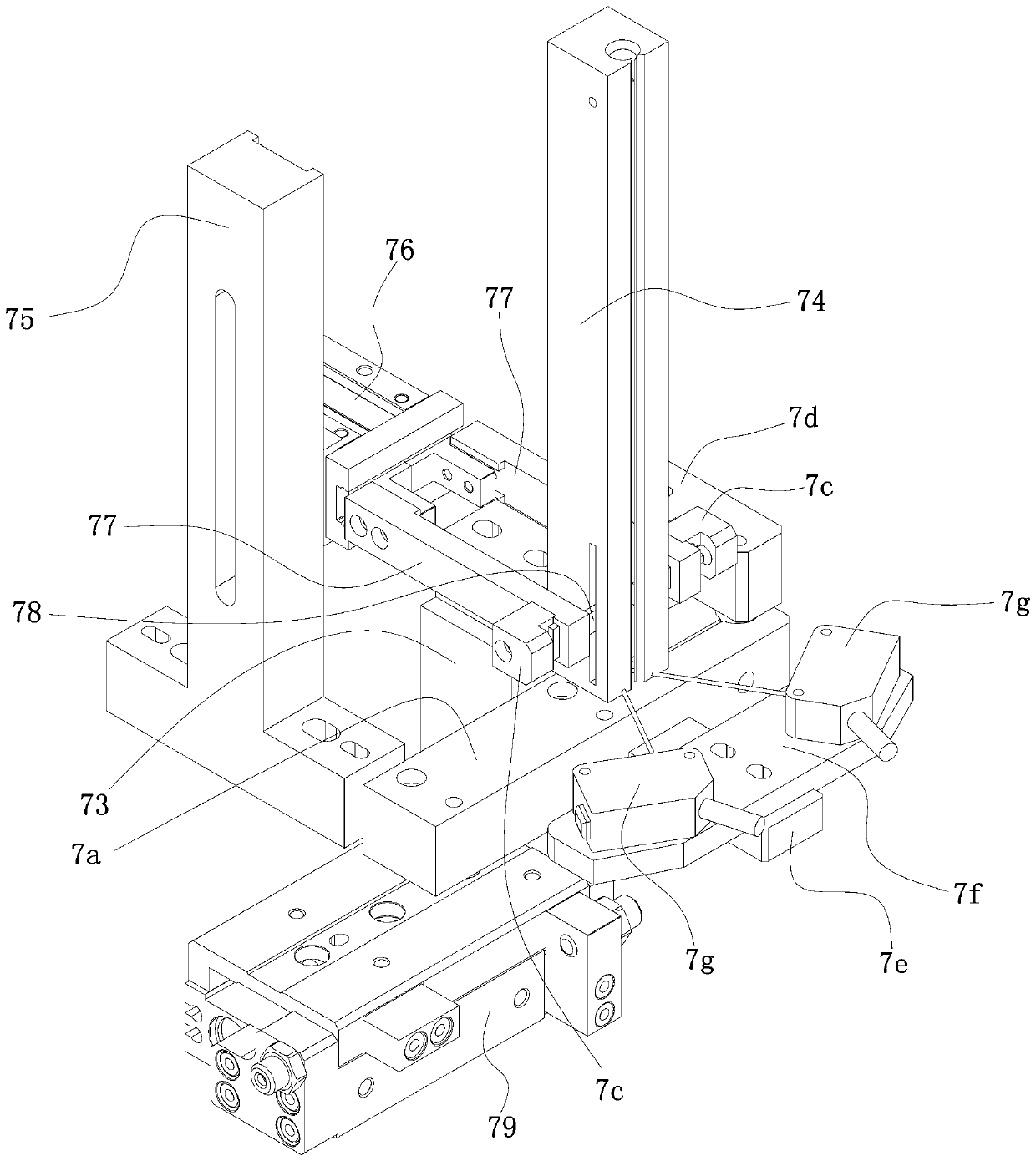
[0047] Such as Figure 1-28 As shown, the present invention relates to the shaft core shaft sleeve assembly equipment of potentiometer or encoder, including main frame 1, on which main frame 1 is provided with a rotating unit 2 through a main workbench 11, and the main workbench 11 around the turn unit 2 is The upper sequence ring is provided with an upper shaft core oiling unit 3, at least two shaft sleeve assembly units 4, a collar installation unit 5 and a feeding unit 6, and the upper shaft core oiling unit 3 is connected with a shaft core delivery unit 7 , each of the bushing assembly units 4 is connected to a bushing delivery unit 8, the collar installation unit 5 is connected to a collar delivery unit 9, and a control unit (not shown) is also arranged on the main workbench 11 ), the control unit is used to start and control each unit of the present in...


PUM


Abstract

The invention discloses assembling equipment for a shaft core and a shaft sleeve of a potentiometer or an encoder. The assembling equipment comprises a main rack, a rotating unit is arranged on the main rack through a main worktable, an upper shaft core oiling unit, two or more shaft sleeve assembling units, a clamp ring mounting unit and a discharging unit are sequentially and annularly arrangedon the position, around the rotating unit, of the main worktable, the upper shaft core oiling unit is connected with a shaft core conveying unit, all the shaft sleeve assembling units are connected with a shaft sleeve conveying unit, and the clamp ring mounting unit is connected with a clamp ring conveying unit. The shaft core and the shaft sleeve are automatically assembled, the time and labor are saved, the assembling efficiency is greatly improved, and the yield of a product is greatly increased.

Description

technical field [0001] The present invention relates to the technical field of mechanical production equipment, in particular to an automatic assembly realized by the mutual cooperation of the upper shaft sleeve oiling unit, the shaft sleeve assembly unit, the collar assembly unit and the blanking unit, which greatly improves the assembly efficiency and saves Time-saving and labor-saving, greatly improving the yield rate of the product, the shaft core shaft sleeve assembly equipment of the potentiometer or encoder. Background technique [0002] The potentiometer (English: Potentiometer) is a kind of variable resistor, usually composed of a resistor body and a rotating or sliding system, that is, a movable contact moves on the resistor body to obtain part of the voltage output. The function of the potentiometer is Adjust the magnitude of voltage (including DC voltage and signal voltage) and current; an encoder (encoder) is a device that compiles and converts signals (such as ...

Claims


Application Information

Patent Timeline
Patent Type & Authority Applications(China)
IPC IPC(8): B23P21/00
Inventor 曾河
Owner 广东钺河智能科技有限公司
Learn More