Supercharge Your Innovation With Domain-Expert AI Agents!

Lifting device and method for hooking or unhooking hanger shaft

A lifting device and hook technology are applied in the directions of load hanging components, transportation and packaging, which can solve the problems of laborious manual operation, high price and low reliability, and achieve simple structure, high operability and reliability, and high cost. low cost effect

Inactive Publication Date: 2019-05-14
POWERCHINA ZHONGNAN ENG
View PDF8 Cites 1 Cited by
  • Summary
  • Abstract
  • Description
  • Claims
  • Application Information

AI Technical Summary

Problems solved by technology

At present, the automatic grabbing beam is divided into two types: lifting device and hydraulic automatic grabbing beam. The lifting device has various forms such as heavy hammer type, ring type, and free hanging type. Manual operation is laborious; the ring-type mechanical grabbing beam relies on spring bayonets to unhook, so the reliability is not high, and the capacity of the ring is not large. In addition, the spring device is easily damaged, and the failure rate is high in complex underwater environments; The free-hanging mechanical grabbing beam is only suitable for large gates due to the large size of the hanging body; the hydraulic automatic grabbing beam has high reliability, but because it contains a hydraulic pump station, and requires power access and waterproof settings, the price is relatively expensive. For large and medium sized gate operations

Method used


Image

  • Lifting device and method for hooking or unhooking hanger shaft
  • Lifting device and method for hooking or unhooking hanger shaft
  • Lifting device and method for hooking or unhooking hanger shaft

Examples


Embodiment 1

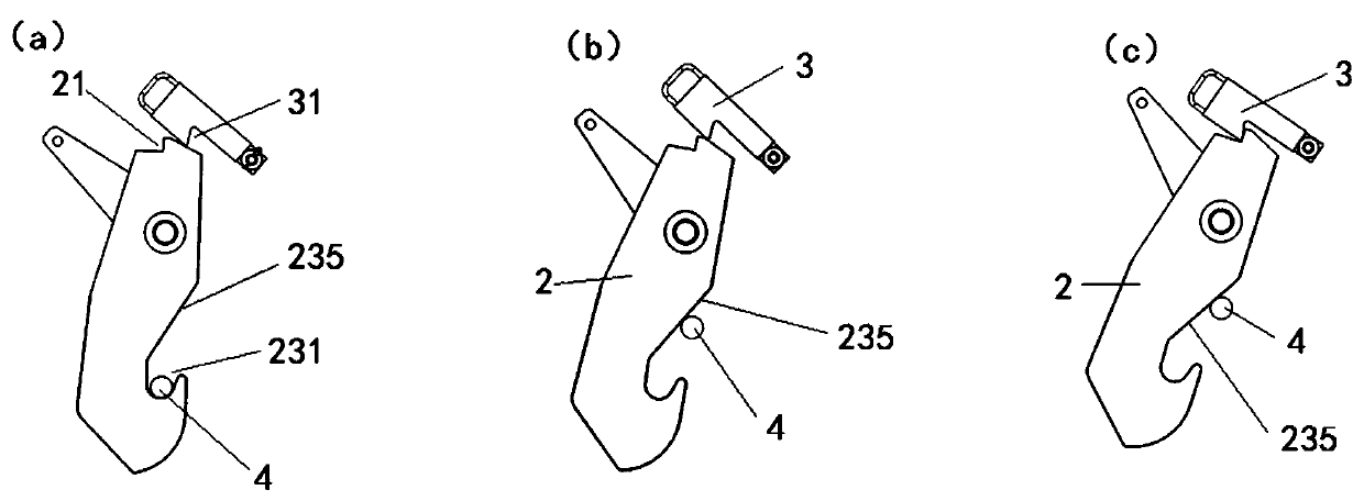
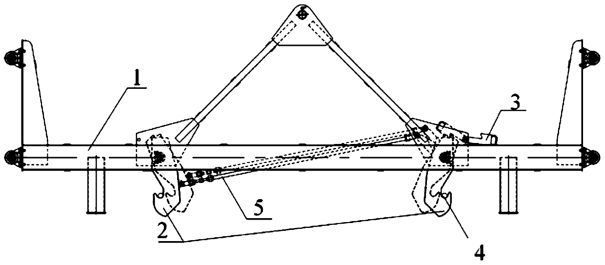
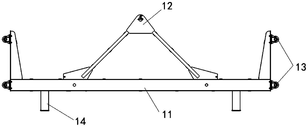
[0031] Such as figure 1 As shown, the lifting device of this embodiment includes a liftable installation part 1, on which a suspension hook 2 and a lock catch 3 are hinged, and the lock catch 3 is located above the suspension hook 2, and the suspension hook 2 and the lock catch 3 are both It can rotate around the hinge point in the vertical plane. The lock catch 3 is provided with a first buckle part 31, and the upper end of the hook 2 is provided with a second buckle part 21 that cooperates with the first buckle part 31. The lock buckle 3 It can be rotated to the non-working position where the first buckle 31 is away from the hook 2, or to the working position where the first buckle 31 is close to the hook 2. When the lock 3 is in the working position, the hook 2 can face the lock 3 Rotate until the first buckle part 31 and the second buckle part 21 are fastened together; specifically, the end of the upper surface of the hook 2 away from the lock buckle 3 is recessed downward...


PUM


Abstract

The invention discloses a lifting device and a method for hooking or unhooking a hanger shaft. The lifting device comprises a mounting part capable of being lifted and lowered, and lifting hooks and buckles are hinged to the mounting part. The buckles are located above the lifting hooks, and the lifting hooks and the buckles are capable of rotating around hinge points in a vertical plane. First clamping buckle parts are disposed on the buckles, and second clamping buckle parts are disposed at the upper ends of the lifting hooks. The buckles can rotate to the non-working positions, away from the lifting hooks, of the first clamping buckle parts, or rotate to the working positions, near the lifting hooks, of the first clamping buckle parts. When the buckles are at the working positions, thelifting hooks can rotate towards the buckles to the first clamping buckle parts and the second clamping buckle parts to be buckled. The lifting hooks can be blocked by the hanger shaft in the descending process so as to rotate to the hanger shaft around the hinge points to enter grooves to realize a hooking state. When the lifting hooks are in the hooking state, the lifting hooks can be blocked bythe hanger shaft while continuing to descend so as to rotate around the hinge points to switch the hooking state to an unhooking state. The buckles buckle the lifting hooks so that the lifting cannotbe reset, and the lifting device can be unhooked.

Description

technical field [0001] The invention relates to the technical field of lifting equipment, in particular to a lifting device and a method for hooking or unhooking a suspension shaft. Background technique [0002] When the hydraulic steel gate is hoisted or lowered, the whole process is mainly operated by the hoist, but the hoist cannot automatically connect with the suspension shaft on the gate when hoisting, and the hoist cannot automatically disengage from the gate after the gate is lowered. Hydraulic steel gates are generally located underwater or in deep gate grooves, and it is difficult to remove and hook the hoist manually. The automatic grab beam is a common auxiliary equipment for lifting or lowering hydraulic steel gates, which can automatically complete the decoupling and hooking operations of the gates. At present, the automatic grabbing beam is divided into two types: lifting device and hydraulic automatic grabbing beam. The lifting device has various forms such ...

Claims


Application Information

Patent Timeline
IPC IPC(8): B66C1/34
Inventor 方作为胡彩石郭熙宏陈辉春虞喜泉
Owner POWERCHINA ZHONGNAN ENG
Features
  • R&D
  • Intellectual Property
  • Life Sciences
  • Materials
  • Tech Scout
  • Unparalleled Data Quality
  • Higher Quality Content
  • 60% Fewer Hallucinations
Learn More