Heat pump system and control method thereof

A heat pump system and control method technology, applied in heat recovery systems, heat pumps, refrigerators, etc., can solve problems such as low temperature, low pressure cavity work, and compressor suction with liquid

Active Publication Date: 2019-05-14
GREE ELECTRIC APPLIANCES INC
View PDF13 Cites 3 Cited by
  • Summary
  • Abstract
  • Description
  • Claims
  • Application Information

AI Technical Summary

Problems solved by technology

[0005] In the prior art, the refrigerant gas flashed by the unit through the flash evaporator is fed into the compressor to increase the discharge capacity of the compressor and reduce the discharge temperature of the compressor to improve the capacity and energy eff

Method used


Image

  • Heat pump system and control method thereof
  • Heat pump system and control method thereof

Examples


Embodiment Construction

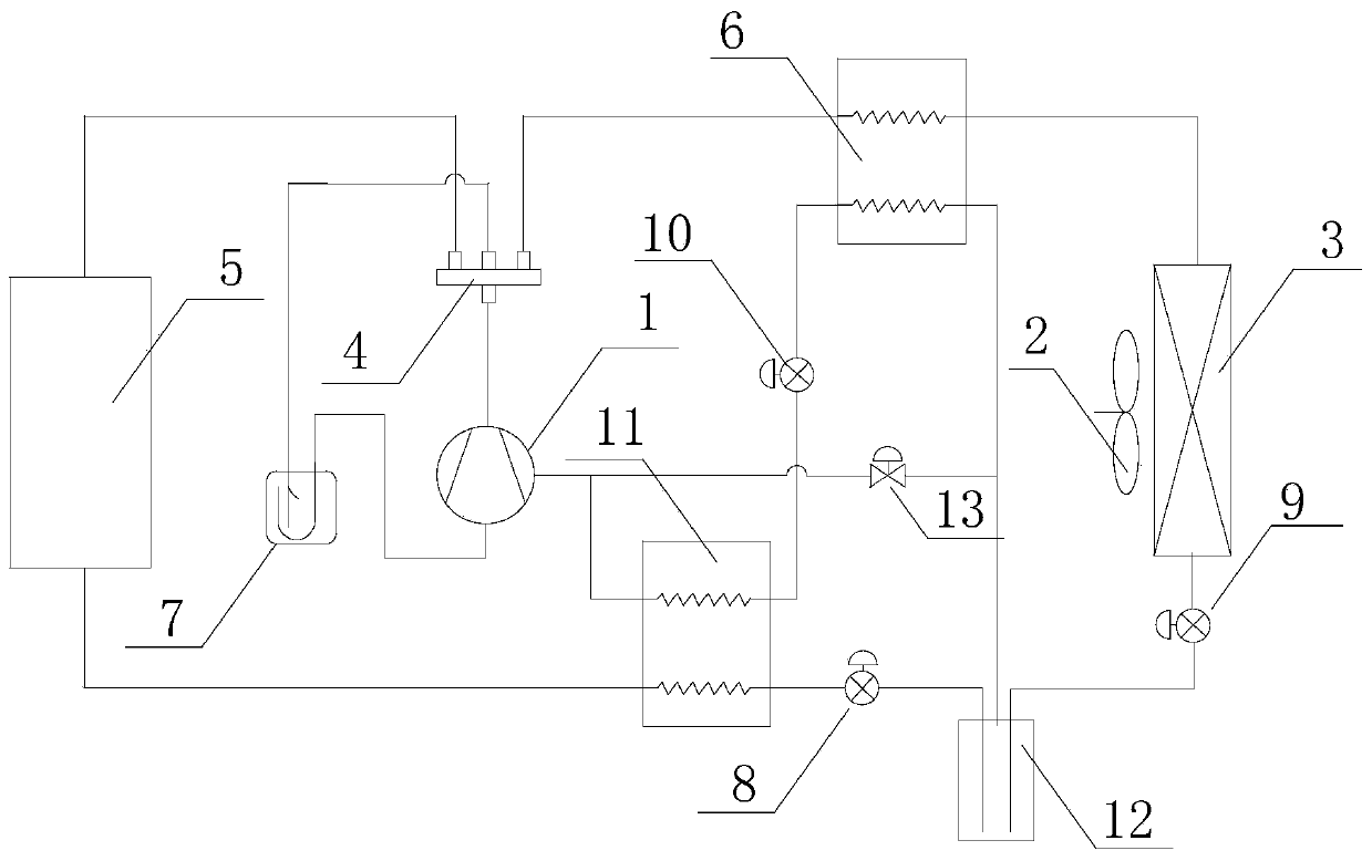
[0031] see in conjunction figure 1 As shown, according to the embodiment of the present invention, the heat pump system includes a compressor 1, a first heat exchanger 3, a first air supply pipeline and a first regenerator 6, and the first end of the first air supply pipeline is connected to the compressor 1, the pipeline between the first heat exchanger 3 and the compressor 1 is the first heat exchange pipeline, and the first heat exchange pipeline and the first air supply pipeline are connected through the first regenerator 6 heat exchange.

[0032] The heat pump system can exchange heat between the refrigerant in the first air supply pipeline and the refrigerant in the first heat exchange pipeline. When the first heat exchange pipeline is connected to the suction port of the compressor 1, the first air supply pipeline The refrigerant can heat the refrigerant in the first heat exchange pipeline, thereby increasing the temperature of the refrigerant entering the suction port...


PUM


Abstract

The invention provides a heat pump system and a control method thereof. The heat pump system comprises a compressor (1), a first heat exchanger (3), a first gas supplementing pipeline and a first heatregenerator (6); the first end of the first gas supplementing pipeline is connected to a gas supplementing port of the compressor (1); a pipeline between the first heat exchanger (3) and the compressor (1) is a first heat exchanging pipeline; and heat exchanging is performed between the first heat exchanging pipeline and the first gas supplementing pipeline through the first heat regenerator (6).The heat pump system can effectively raise the gas sucking temperature of the compressor, it is avoided that liquid is taken during gas sucking of the compressor, the gas sucking superheat degree isimproved, and the unit heating capacity is increased.

Description

technical field [0001] The invention belongs to the technical field of air conditioning, and in particular relates to a heat pump system and a control method thereof. Background technique [0002] For air source heat pump products, the problem of how to keep the heating capacity of the unit without attenuation or less attenuation in low temperature or even ultra-low temperature environment is a problem that manufacturers focus on and need to solve. [0003] Due to the (ultra) low temperature environment, the heat exchange capacity of the outdoor heat exchanger is low, and the evaporation temperature is low, resulting in low suction temperature of the compressor, high discharge temperature, and reduced energy efficiency of the whole machine. [0004] At present, many products adopt the technology of supplementing air to increase enthalpy to improve the heating capacity of the unit under low temperature conditions. [0005] In the prior art, the refrigerant gas flashed by the...

Claims


Application Information

Patent Timeline
IPC IPC(8): F25B30/06F25B49/02F25B41/06F25B41/30
CPCY02B30/52
Inventor 李天阳王东雷二桥王丽阳
Owner GREE ELECTRIC APPLIANCES INC
Why Eureka
Try Eureka