Air source co2 heat pump system for preventing evaporator from frosting by using heat of heat regenerator

Active Publication Date: 2022-08-04
TSINGHUA UNIV +1
View PDF10 Cites 0 Cited by
  • Summary
  • Abstract
  • Description
  • Claims
  • Application Information

AI Technical Summary

Benefits of technology

[0012]The air source CO2 heat pump system for preventing evaporator from frosting by using heat of a heat regenerator, proposed by the present disclosure, has the following advantages.
[0013]In the air source CO2 heat pump system for preventing evaporator from frosting by using heat of a heat regenerator, by means of the regenerative heat exchange tank, on the one hand, the temperature drop of regenerative heat of the system is further increased and throttling loss is reduced, which improves the system performance; on the other hand, the heat generated by the temperature drop of regenerative heat is configured for heat storage used for defrosting, and for overheating temperature rise, so as to avoid a too big degree of superhea

Problems solved by technology

In practical engineering, the use of heat pumps for heating often leads to the problem of “pulling a small carriage by a big horse” between the selected system and the demands of heat loads.
For constant frequency heat pump units, they will frequently start and stop, which leads to increased energy consumption, large start and stop noise and can easily cause damage to the system.
For the variable frequency heat pump units, they may work under partial loads for a long time, and the change of load gradually increases the return water temperature of the system, which attenuates the system performance seriously, has large power consumption and poor energy-saving eff

Method used


Image

  • Air source co2 heat pump system for preventing evaporator from frosting by using heat of heat regenerator
  • Air source co2 heat pump system for preventing evaporator from frosting by using heat of heat regenerator
  • Air source co2 heat pump system for preventing evaporator from frosting by using heat of heat regenerator

Examples


Embodiment Construction

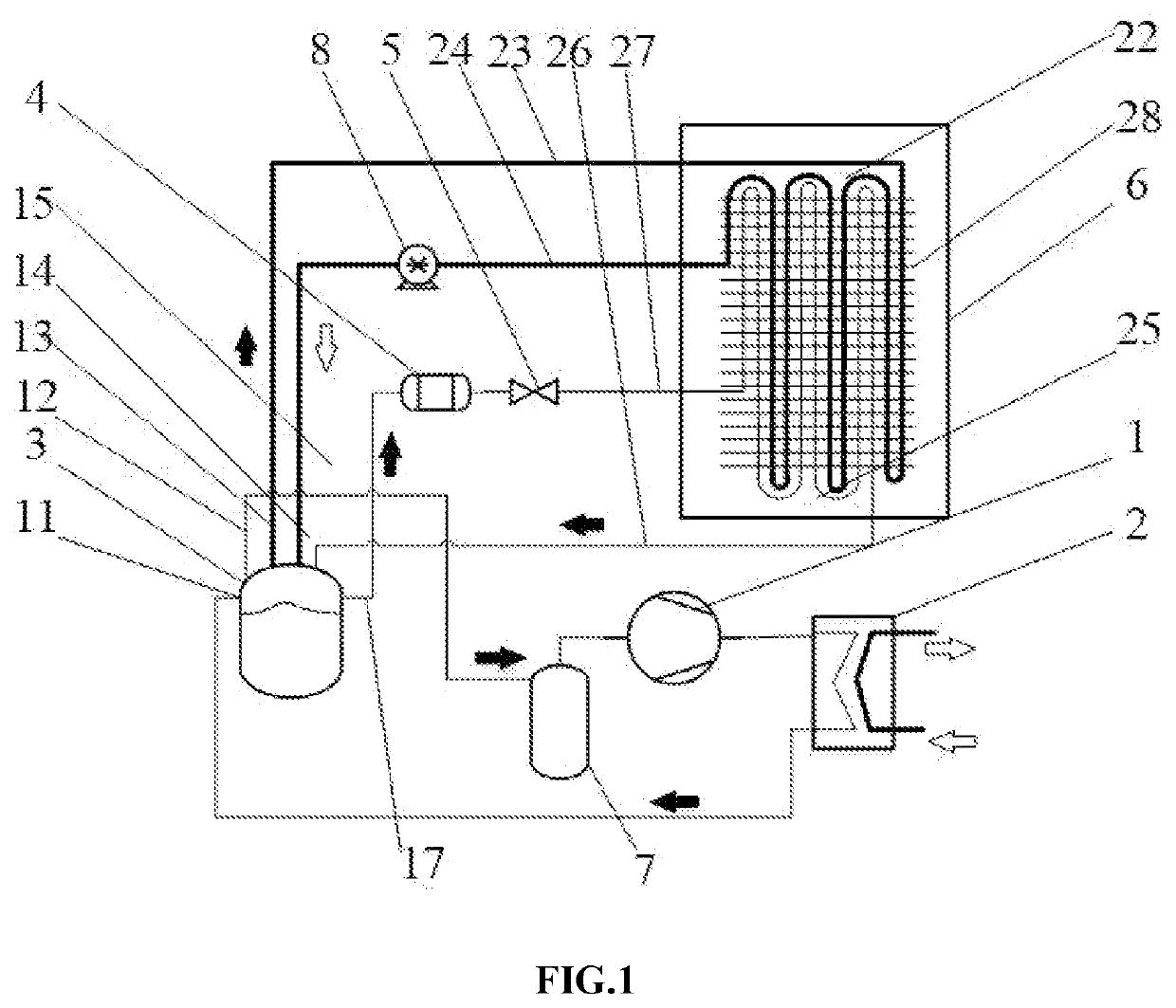
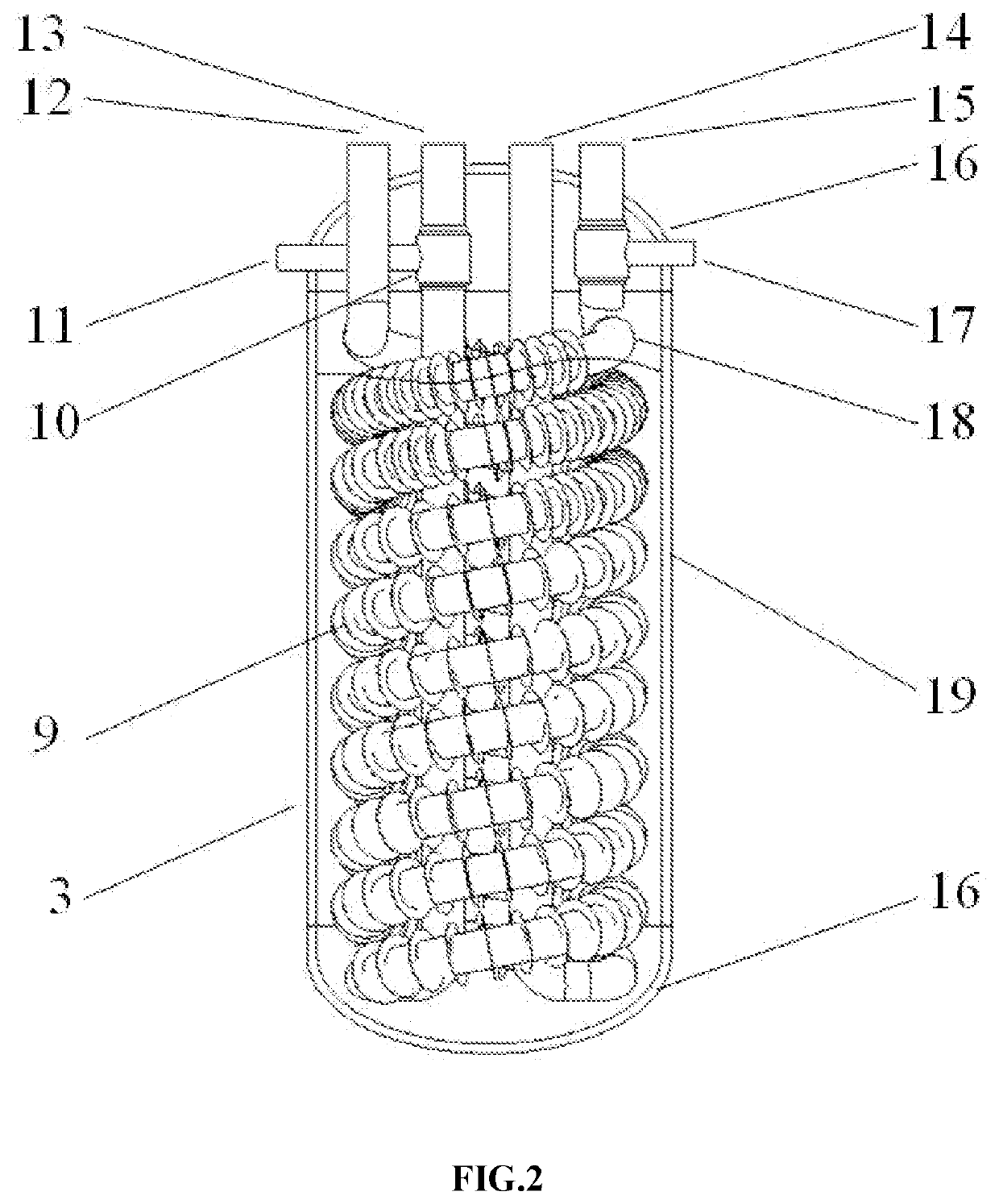
[0019]A structure of the air source CO2 heat pump system for preventing evaporator from frosting by using heat of a heat regenerator, provided by the present disclosure, is shown in FIG. 1. The air source CO2 heat pump system includes an air source heat pump system, a regenerative heat exchange tank 3 and a cooling pump 8. The air source heat pump system includes a compressor 1, a gas cooler 2, an expansion valve 5, an air-cooled evaporator 6, a drying filter 4 and a gas-liquid separator 7. The structure of the regenerative heat exchange tank 3 is shown in FIG. 2. The tank body 19 of the regenerative heat exchange tank 3 is filled with a phase change material. A tube-in-tube internal heat exchanger 10 and a cooling liquid heat exchange tube of single-spiral finned tube type 18 are provided within the tank body 19 of the regenerative heat exchange tank 3. The tube-in-tube internal heat exchanger 10 and the cooling liquid heat exchange tube of single-spiral finned tube type 18 are ins...


PUM


Abstract

The present disclosure relates to the technical field of heat pumps, in particular to an air source CO2 heat pump system for preventing an evaporator from frosting by using heat of a heat regenerator. The air source CO2 heat pump system mainly includes an air source heat pump system, a regenerative heat exchange tank and a cooling pump. Through the regenerative heat exchange tank, on the one hand, the temperature drop of regenerative heat of the system is further increased and throttling loss is reduced; on the other hand, the heat generated by the regenerative temperature drop is configured for heat storage used for defrosting, and configured for overheating temperature rise.

Description

CROSS REFERENCE TO RELATED APPLICATION[0001]This patent application claims the benefit and priority of Chinese Patent Application No. 202110131222.7 filed on Jan. 30, 2021, the disclosure of which is incorporated by reference herein in its entirety as part of the present application.TECHNICAL FIELD[0002]The present disclosure relates to the technical field of heat pumps, in particular to an air source CO2 heat pump system for preventing evaporator from frosting by using heat of heat regenerator.BACKGROUND ART[0003]In order to improve the level of cleanness of heating in northern regions and reduce the emission of air pollutants, 10 departments such as the National Development and Reform Commission and the National Energy Administration have formulated “Plan for Clean Heating in Winter in Northern Regions (2017-2021)”. The Plan points out that the area heated electrically would reach 1,500,000,000 square meters by 2021, including 500,000,000 square meters heated by heat pumps. In Mar...

Claims


Application Information

Patent Timeline
IPC IPC(8): F25B9/08F25B29/00
CPCF25B9/08F25B2309/06F25B29/003F25B47/006F25B40/06F24D15/04F24D2200/123F25B9/008F25B40/00F25B25/005F25B30/02F25B2400/053F25B2400/054F25B2400/24F25B2400/16F25B2309/061F25D21/12F25B2400/05
Inventor ZHU, YINHAIJIANG, PEIXUELI, CONGHUI
Owner TSINGHUA UNIV
Why Eureka
Try Eureka