Cascade compression refrigeration system and refrigeration equipment with same

A compression refrigeration, cascading technology, applied in refrigerators, compressors, refrigeration and liquefaction, etc., can solve the problems of condensation at the suction port of low-temperature compressors, reduced refrigeration efficiency, low suction temperature, etc., to improve operation performance, increase the suction temperature, and improve the cooling efficiency

Pending Publication Date: 2021-09-24
QINGDAO HAIER SMART TECH R & D CO LTD +1
View PDF0 Cites 0 Cited by
  • Summary
  • Abstract
  • Description
  • Claims
  • Application Information

AI Technical Summary

Problems solved by technology

[0003] In the prior art, in the low-temperature stage refrigeration cycle circuit, the temperature of the second refrigerant flowing from the return air pipe to the suction port of the low-temperature stage compressor is relatively low, so that the suction temperature of the compressor in the low-temperature part is low, which will cause the return of the low-temperature stage compressor. Condensation or frost around air ducts and cryogenic stage compressor suction leading to loss of cooling capacity
For small domestic refrigeration equipment, a cooling loss of more than ten watts or even a few watts will lead to a significant reduction in cooling efficiency

Method used


Image

  • Cascade compression refrigeration system and refrigeration equipment with same
  • Cascade compression refrigeration system and refrigeration equipment with same
  • Cascade compression refrigeration system and refrigeration equipment with same

Examples


Embodiment Construction

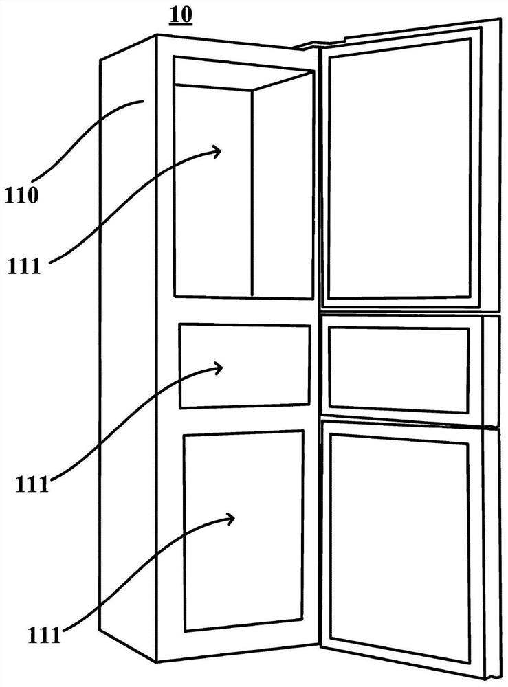
[0030] figure 1 is a schematic diagram of a refrigeration device 10 with a cascade compression refrigeration system according to one embodiment of the present invention.

[0031] The refrigerating device 10 may be a small domestic refrigerating device for storing foodstuffs, medicines, or other items, for example, it may be a refrigerator or a freezer.

[0032] Although the cascade compression refrigeration system has been involved in large-scale refrigeration equipment, however, due to the excessive operating noise and high energy consumption of the existing cascade compression refrigeration system, the cascade compression refrigeration system in the prior art The system has been unable to be applied to household small refrigeration equipment.

[0033] The cascade compression refrigeration system of this embodiment is especially suitable for small domestic refrigeration equipment 10, such as a refrigerator.

[0034] The refrigeration device 10 in this embodiment takes a ref...


PUM


Abstract

The invention provides a cascade compression refrigeration system and refrigeration equipment with the cascade compression refrigeration system. The cascade compression refrigeration system comprises a high-temperature-stage refrigeration circulation loop and a low-temperature-stage refrigeration circulation loop, wherein the high-temperature-stage refrigeration circulation loop is used for circulating a first refrigerant; an evaporation part is arranged in the high-temperature-stage refrigeration circulation loop; the low-temperature-stage refrigeration circulation loop is used for circulating a second refrigerant; a low-temperature-stage compressor, a condensation part, a low-temperature-stage evaporation pipe and a heat exchange assembly are arranged in the low-temperature-stage refrigeration circulation loop; the heat exchange assembly comprises a heat releasing part and a heat absorption part; the heat releasing part is arranged between an exhaust port of the low-temperature-stage compressor and the condensation part; the heat absorption part is arranged between the low-temperature-stage evaporation pipe and a suction inlet of the low-temperature-stage compressor; the heat absorption part is used for enabling the second refrigerant flowing through the heat absorption part to absorb the heat of the second refrigerant flowing through the heat releasing part to increase the temperature, so that the air suction temperature of the low-temperature-stage compressor can be increased, and the heat load of the high-temperature-stage refrigeration circulation loop can be reduced.

Description

technical field [0001] The invention relates to the field of refrigeration, in particular to a cascaded compression refrigeration system and refrigeration equipment with it. Background technique [0002] The cascade compression refrigeration system usually consists of two separate refrigeration cycles, which are called the high-temperature stage refrigeration cycle (referred to as the high-temperature part) and the low-temperature stage refrigeration cycle (referred to as the low-temperature part). The high-temperature part uses a first refrigerant with a relatively high standard boiling point, and the low-temperature part uses a second refrigerant with a relatively low standard boiling point. The condensing evaporator uses the cold produced by the first refrigerant in the high temperature part to condense the second refrigerant vapor discharged from the compressor in the low temperature part. It is both an evaporator in the high temperature part and a condenser in the low t...

Claims


Application Information

Patent Timeline
Patent Type & Authority Applications(China)
IPC IPC(8): F25B7/00F25D11/02F25D19/04F25D21/04
CPCF25B7/00F25D11/025F25D19/04F25D21/04
Inventor 赵向辉孙永升陶瑞涛刘煜森冯茹丹
Owner QINGDAO HAIER SMART TECH R & D CO LTD
Why Eureka
Try Eureka